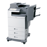
Operator panel cover latch assembly removal (models X651, X652, X654,
X656)
1 Lift the operator panel cover assembly.
2 Remove the ten screws (A) securing the operator panel cover latch assembly to the operator panel cover
assembly.
A
A
3 Remove the operator panel cover latch assembly.
Operator panel door assembly removal (models X651, X652, X654,X656)
Warning—Potential Damage: When replacing the operator panel assembly or the system card assembly,
only replace one component at a time. Replace the required component and perform a POR before replacing
another component. If this procedure is not followed, the printer will be rendered inoperable. Never replace
two or more components without a POR after installing each one or the printer will be rendered inoperable.
Never install and remove the components as a method of troubleshooting components. Once a component
has been installed in a machine, it cannot be used in another machine. It must be returned to the
manufacturer.
1 Remove the laser cover. Go to “Laser cover removal (models X651, X652, X654, and X656)” on page
325.
2 Remove the counter balance springs (A) on both sides.
3 Remove the print cartridge cover springs (B) on both sides.
4 Remove the E‑clips (C) on both sides securing the links to the hinges, and remove the links.
7462
Repair information
345
 Loading...