UM10375 All information provided in this document is subject to legal disclaimers. © NXP B.V. 2011. All rights reserved.
User manual Rev. 3 — 14 June 2011 116 of 368
NXP Semiconductors
UM10375
Chapter 7: LPC13xx I/O configuration
7.4.43 IOCON_SCK0_LOC
This register is used to select a pin among three possible choices for the SSP0 SCK0
function.
Remark: Note that once the pin location has been selected, the function still must be set
to SCK0 in the corresponding IOCONF registers for the SCK0 to be usable on that pin.
7.4.44 IOCON_DSR_LOC
Remark: For the LPC1311/01 and LPC1313/01 parts, the modem functions on pins
PIO3_1 to PIO3_3 must be configured in the corresponding IOCONFIG registers and also
in the IOCON_DSR_LOC, IOCON_DCD_LOC, and IOCON_RI_LOC registers (see
Table 140
to Table 101).
7.4.45 IOCON_DCD_LOC
Remark: For the LPC1311/01 and LPC1313/01 parts, the modem functions on pins
PIO3_1 to PIO3_3 must be configured in the corresponding IOCONFIG registers and also
in the IOCON_DSR_LOC, IOCON_DCD_LOC, and IOCON_RI_LOC registers (see
Table 140
to Table 101).
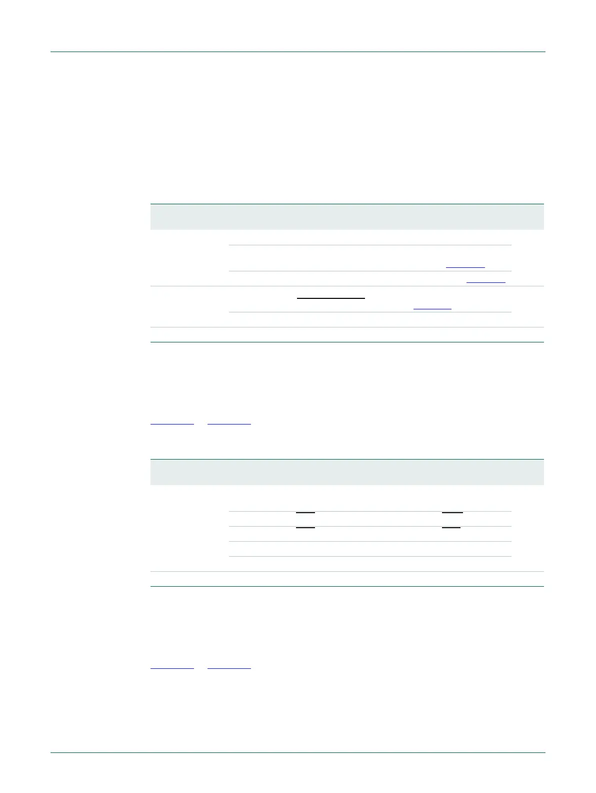
Table 139. IOCON SCK0 location register (IOCON_SCK0_LOC, address 0x4004 40B0) bit
description
Bit Symbol Value Description Reset
value
1:0 SCKLOC Selects pin location for SCK0 pin. 0
0x0 Selects SCK0 function for pin
SWCLK/PIO0_10/SCK0/CT16B0_MAT2 (see Table 121
).
0x1 Selects SCK0 function for pin PIO2_11/SCK0 (see Table 123
0x2 Selects SCK0 function for pin
PIO0_6/USB_CONNECT/SCK0 (see Ta ble 114).
0x3 Reserved.
31:2 - - Reserved -
Table 140. IOCON DSR location register (IOCON_DSR_LOC, address 0x4004 40B4) bit
description
Bit Symbol Value Description Reset
value
1:0 DSRLOC Selects pin location for DSR0 pin (this register is only used for
parts LPC1311/01 and LPC1313/01).
00
0x0 Selects DSR
function in pin location PIO2_1/DSR/SCK1.
0x1 Selects DSR
function in pin location PIO3_1/DSR.
0x2 Reserved.
0x3 Reserved.
31:2 - - Reserved. -

 Loading...