UM10375 All information provided in this document is subject to legal disclaimers. © NXP B.V. 2011. All rights reserved.
User manual Rev. 3 — 14 June 2011 22 of 368
NXP Semiconductors
UM10375
Chapter 3: LPC13xx System configuration
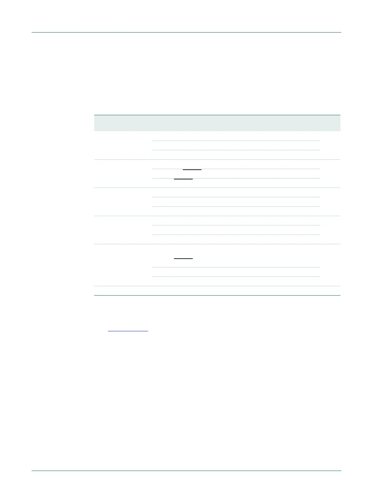
3.5.10 System reset status register
The SYSRSTSTAT register shows the source of the latest reset event. The bits are
cleared by writing a one to any of the bits. The POR event clears all other bits in this
register, but if another reset signal (e.g., EXTRST) remains asserted after the POR signal
is negated, then its bit is set to detected.
3.5.11 System PLL clock source select register
This register selects the clock source for the system PLL. The SYSPLLCLKUEN register
(see Section 3.5.12
) must be toggled from LOW to HIGH for the update to take effect.
Remark: The system oscillator must be selected if the system PLL is used to generate a
48 MHz clock to the USB block.
Remark: When switching clock sources, both clocks must be running before the clock
source is updated.
Table 17. System reset status register (SYSRESSTAT, address 0x4004 8030) bit description
Bit Symbol Value Description Reset
value
0 POR POR reset status 0x0
0 No POR detected
1 POR detected
1 EXTRST 0x0
0 No RESET
event detected
1 RESET
detected
2 WDT Status of the Watchdog reset 0x0
0 No WDT reset detected
1 WDT reset detected
3 BOD Status of the Brown-out detect reset 0x0
0 No BOD reset detected
1 BOD reset detected
4 SYSRST Status of the software system reset. The ARM software
reset has the same effect as the hardware reset using the
RESET
pin.
0x0
0 No System reset detected
1 System reset detected
31:5 - - Reserved 0x00