UM10375 All information provided in this document is subject to legal disclaimers. © NXP B.V. 2011. All rights reserved.
User manual Rev. 3 — 14 June 2011 125 of 368
NXP Semiconductors
UM10375
Chapter 8: LPC13xx Pin configuration
PIO1_5/RTS/
CT32B0_CAP0
45
[3]
yes I/O I; PU PIO1_5 — General purpose digital input/output pin.
O- RTS
— Request To Send output for UART.
I- CT32B0_CAP0 — Capture input 0 for 32-bit timer 0.
PIO1_6/RXD/
CT32B0_MAT0
46
[3]
yes I/O I; PU PIO1_6 — General purpose digital input/output pin.
I- RXD — Receiver input for UART.
O- CT32B0_MAT0 — Match output 0 for 32-bit timer 0.
PIO1_7/TXD/
CT32B0_MAT1
47
[3]
yes I/O I; PU PIO1_7 — General purpose digital input/output pin.
O- TXD — Transmitter output for UART.
O- CT32B0_MAT1 — Match output 1 for 32-bit timer 0.
PIO1_8/CT16B1_CAP0 9
[3]
yes I/O I; PU PIO1_8 — General purpose digital input/output pin.
I- CT16B1_CAP0 — Capture input 0 for 16-bit timer 1.
PIO1_9/CT16B1_MAT0 17
[3]
yes I/O I; PU PIO1_9 — General purpose digital input/output pin.
O- CT16B1_MAT0 — Match output 0 for 16-bit timer 1.
PIO1_10/AD6/
CT16B1_MAT1
30
[5]
yes I/O I; PU PIO1_10 — General purpose digital input/output pin.
I- AD6 — A/D converter, input 6.
O- CT16B1_MAT1 — Match output 1 for 16-bit timer 1.
PIO1_11/AD7 42
[5]
yes I/O I; PU PIO1_11 — General purpose digital input/output pin.
I- AD7 — A/D converter, input 7.
PIO2_0/DTR
/SSEL1 2
[3]
yes I/O I; PU PIO2_0 — General purpose digital input/output pin.
O- DTR
— Data Terminal Ready output for UART.
I/O - SSEL1 — Slave Select for SSP1 (LPC1313FBD48/01 only).
PIO2_1/DSR
/SCK1 13
[3]
yes I/O I; PU PIO2_1 — General purpose digital input/output pin.
I- DSR
— Data Set Ready input for UART.
I/O - SCK1 — Serial clock for SSP1 (LPC1313FBD48/01 only).
PIO2_2/DCD
/MISO1 26
[3]
yes I/O I; PU PIO2_2 — General purpose digital input/output pin.
I- DCD
— Data Carrier Detect input for UART.
I/O - MISO1 — Master In Slave Out for SSP1 (LPC1313FBD48/01 only).
PIO2_3/RI
/MOSI1 38
[3]
yes I/O I; PU PIO2_3 — General purpose digital input/output pin.
I- RI
— Ring Indicator input for UART.
I/O - MOSI1 — Master Out Slave In for SSP1 (LPC1313FBD48/01 only).
PIO2_4 18
[3]
yes I/O I; PU PIO2_4 — General purpose digital input/output pin (LPC1343 only).
PIO2_4 19
[3]
yes I/O I; PU PIO2_4 — General purpose digital input/output pin (LPC1313 only).
PIO2_5 21
[3]
yes I/O I; PU PIO2_5 — General purpose digital input/output pin (LPC1343 only).
PIO2_5 20
[3]
yes I/O I; PU PIO2_5 — General purpose digital input/output pin (LPC1313 only).
PIO2_6 1
[3]
yes I/O I; PU PIO2_6 — General purpose digital input/output pin.
PIO2_7 11
[3]
yes I/O I; PU PIO2_7 — General purpose digital input/output pin.
PIO2_8 12
[3]
yes I/O I; PU PIO2_8 — General purpose digital input/output pin.
PIO2_9 24
[3]
yes I/O I; PU PIO2_9 — General purpose digital input/output pin.
PIO2_10 25
[3]
yes I/O I; PU PIO2_10 — General purpose digital input/output pin.
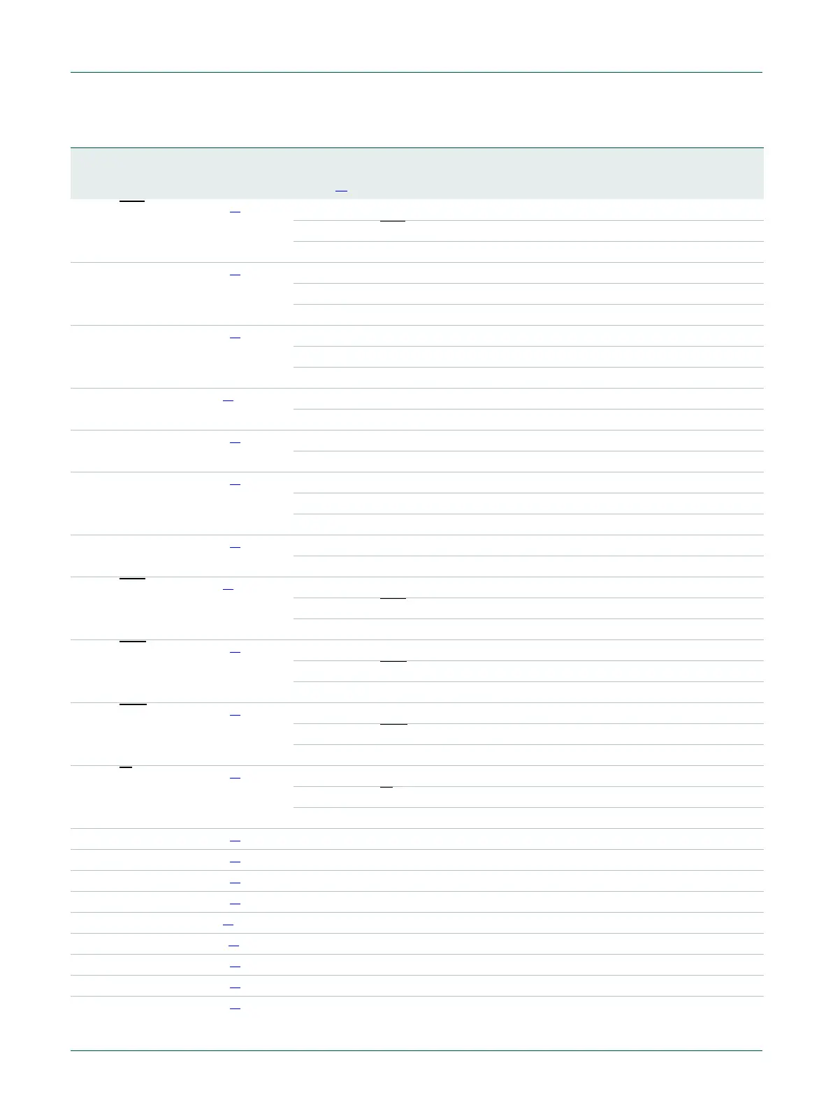
Table 144. LPC1313/42/43 LQFP48 pin description table
…continued
Symbol Pin Start
logic
input
Type Reset
state
[1]
Description
 Loading...

