UM10375 All information provided in this document is subject to legal disclaimers. © NXP B.V. 2011. All rights reserved.
User manual Rev. 3 — 14 June 2011 91 of 368
NXP Semiconductors
UM10375
Chapter 7: LPC13xx I/O configuration
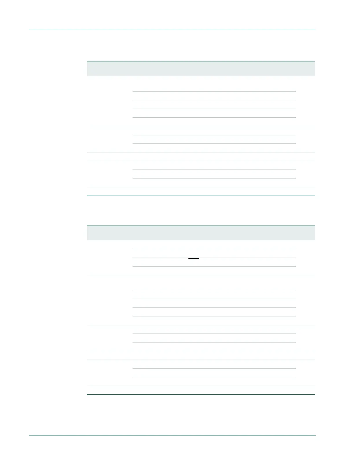
7.4.2 IOCON_PIO2_0
4:3 MODE Selects function mode (on-chip pull-up/pull-down resistor
control).
10
0x0 Inactive (no pull-down/pull-up resistor enabled)
0x1 Pull-down resistor enabled
0x2 Pull-up resistor enabled
0x3 Repeater mode
5 HYS Hysteresis 0
0 Disable
1 Enable
9:6 - - Reserved 0011
10 OD Selects pseudo open-drain mode. 0
0 Standard GPIO output
1 Open-drain output
31:11 - - Reserved -
Table 97. IOCON_PIO2_6 register (IOCON_PIO2_6, address 0x4004 4000) bit description
Bit Symbol Value Description Reset
value
Table 98. IOCON_PIO2_0 register (IOCON_PIO2_0, address 0x4004 4008) bit description
Bit Symbol Value Description Reset
value
2:0 FUNC Selects pin function. All other values are reserved. 000
0x0 Select function PIO2_0.
0x1 Select function DTR
.
0x2 Select function SSEL1 (function not available on all parts).
4:3 MODE Selects function mode (on-chip pull-up/pull-down resistor
control)
10
0x0 Inactive (no pull-down/pull-up resistor enabled)
0x1 Pull-down resistor enabled
0x2 Pull-up resistor enabled
0x3 Repeater mode
5 HYS Hysteresis 0
0 Disable
1 Enable
9:6 - - Reserved 0011
10 OD Selects pseudo open-drain mode. 0
0 Standard GPIO output
1 Open-drain output
31:11 - - Reserved -