UM10375 All information provided in this document is subject to legal disclaimers. © NXP B.V. 2011. All rights reserved.
User manual Rev. 3 — 14 June 2011 19 of 368
NXP Semiconductors
UM10375
Chapter 3: LPC13xx System configuration
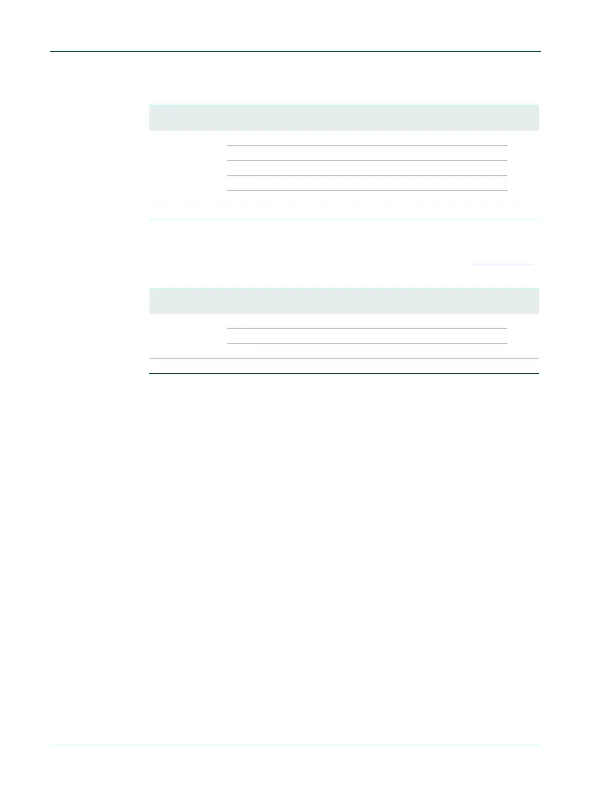
3.5.6 USB PLL status register
This register is a Read-only register and supplies the PLL lock status (see Section 3.11.1).
6:5 PSEL Post divider ratio P. The division ratio is 2 P. 0x00
0x0 P = 1
0x1 P = 2
0x2 P = 4
0x3 P = 8
31:7 - - Reserved. Do not write ones to reserved bits. 0x00
Table 12. USB PLL control register (USBPLLCTRL, address 0x4004 8010) bit description
Bit Symbol Value Description Reset
value
Table 13. USB PLL status register (USBPLLSTAT, address 0x4004 8014) bit description
Bit Symbol Value Description Reset
value
0 LOCK PLL lock status 0x0
0 PLL not locked
1 PLL locked
31:1 - - Reserved 0x00
 Loading...

