UM10375 All information provided in this document is subject to legal disclaimers. © NXP B.V. 2011. All rights reserved.
User manual Rev. 3 — 14 June 2011 191 of 368
NXP Semiconductors
UM10375
Chapter 12: LPC13xx UART
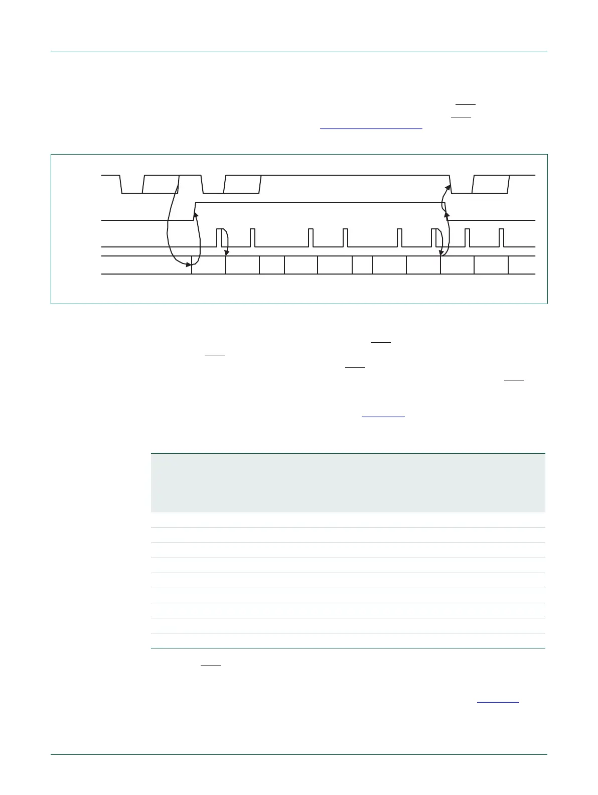
Example: Suppose the UART operating in type ‘550 mode has the trigger level in U0FCR
set to 0x2, then, if Auto-RTS is enabled, the UART will de-assert the RTS
output as soon
as the receive FIFO contains 8 bytes (Table 201 on page 188
). The RTS output will be
reasserted as soon as the receive FIFO hits the previous trigger level: 4 bytes.
12.6.8.1.2 Auto-CTS
The Auto-CTS function is enabled by setting the CTSen bit. If Auto-CTS is enabled, the
transmitter circuitry in the U0TSR module checks CTS
input before sending the next data
byte. When CTS
is active (low), the transmitter sends the next byte. To stop the
transmitter from sending the following byte, CTS
must be released before the middle of
the last stop bit that is currently being sent. In Auto-CTS mode, a change of the CTS
signal does not trigger a modem status interrupt unless the CTS Interrupt Enable bit is set,
Delta CTS bit in the U0MSR will be set though. Table 204
lists the conditions for
generating a Modem Status interrupt.
The auto-CTS function reduces interrupts to the host system. When flow control is
enabled, a CTS
state change does not trigger host interrupts because the device
automatically controls its own transmitter. Without Auto-CTS, the transmitter sends any
data present in the transmit FIFO and a receiver overrun error can result. Figure 21
illustrates the Auto-CTS functional timing.
Fig 20. Auto-RTS Functional Timing
start byte N stop start bits0..7 stop start bits0..7 stop
N-1
N
N-1 N-1N-2 N-2 M+2 M+1 M M-1
UART Rx
RTS pin
UART Rx
FIFO level
UART Rx
FIFO read
~
~
~
~
~
~
~
~
~
~
Table 204. Modem status interrupt generation
Enable
modem
status
interrupt
(U0ER[3])
CTSen
(U0MCR[7])
CTS
interrupt
enable
(U0IER[7])
Delta CTS
(U0MSR[0])
Delta DCD or trailing edge
RI or
Delta DSR (U0MSR[3] or
U0MSR[2] or U0MSR[1])
Modem
status
interrupt
0x x x x No
10 x 0 0 No
10 x 1 x Yes
10 x x 1 Yes
11 0 x 0 No
11 0 x 1 Yes
11 1 0 0 No
11 1 1 x Yes
11 1 x 1 Yes