UM10375 All information provided in this document is subject to legal disclaimers. © NXP B.V. 2011. All rights reserved.
User manual Rev. 3 — 14 June 2011 219 of 368
NXP Semiconductors
UM10375
Chapter 13: LPC13xx I2C-bus controller
When the slave address and data direction bit have been transmitted and an
acknowledge bit has been received, the SI bit is set, and the Status Register will show the
status code. For master mode, the possible status codes are 0x40, 0x48, or 0x38. For
slave mode, the possible status codes are 0x68, 0x78, or 0xB0. For details, refer to
Table 236
.
After a Repeated START condition, I
2
C may switch to the master transmitter mode.
13.9.3 Slave Receiver mode
In the slave receiver mode, data bytes are received from a master transmitter. To initialize
the slave receiver mode, write any of the Slave Address registers (I2ADR0-3) and write
the I
2
C Control Set register (I2CONSET) as shown in Table 230.
I2EN must be set to 1 to enable the I
2
C function. AA bit must be set to 1 to acknowledge
its own slave address or the General Call address. The STA, STO and SI bits are set to 0.
After I2ADR and I2CONSET are initialized, the I
2
C interface waits until it is addressed by
its own address or general address followed by the data direction bit. If the direction bit is
0 (W), it enters slave receiver mode. If the direction bit is 1 (R), it enters slave transmitter
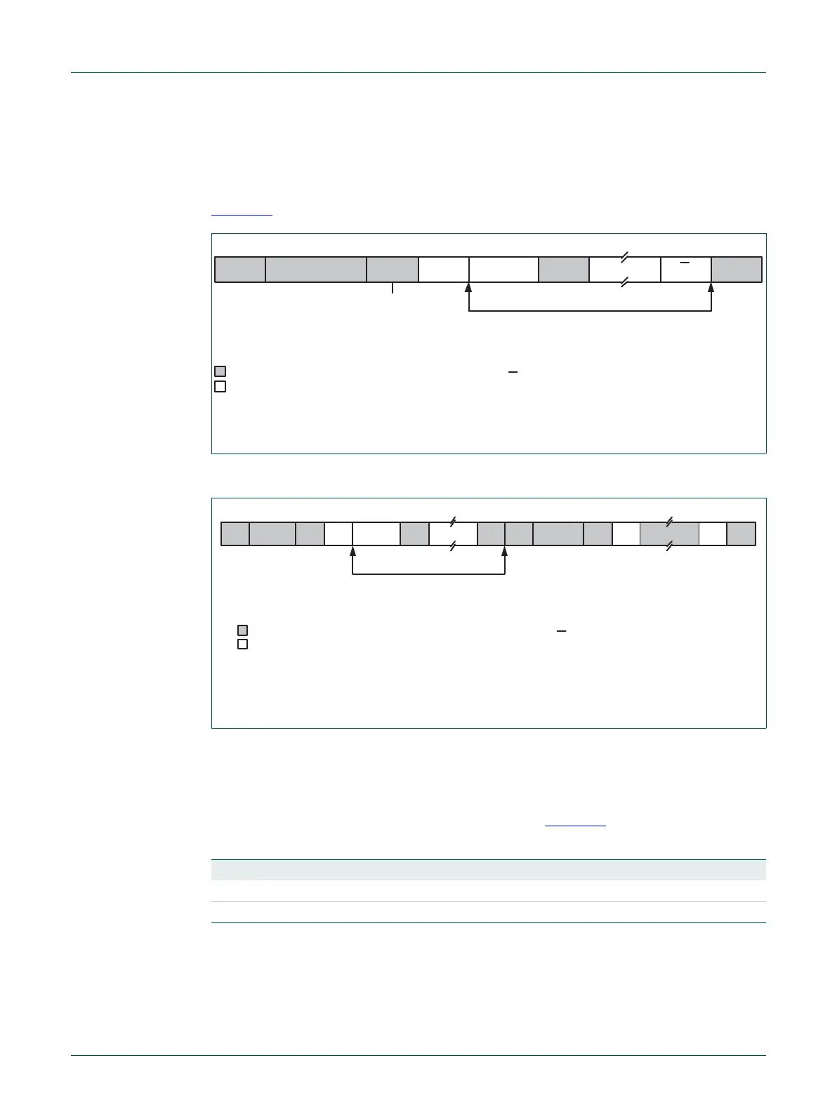
Fig 27. Format of Master Receiver mode
Fig 28. A Master Receiver switches to Master Transmitter after sending Repeated START
DATA
A = Acknowledge (SDA low)
A = Not acknowledge (SDA high)
S = START condition
P = STOP condition
S SLAVE ADDRESS R A DATA P
data transferred
(n Bytes + Acknowledge)
“0” - write
“1” - read
from Master to Slave
from Slave to Master
A
A
A = Acknowledge (SDA low)
A = Not acknowledge (SDA high)
S = START condition
P = STOP condition
SLA = Slave Address
DATA
data transferred
(n Bytes + Acknowledge)
From master to slave
From slave to master
A DATA A ASLA R RS W PS SLA DATAAA
Table 230. I2C0CONSET and I2C1CONSET used to configure Slave mode
Bit 7 6 5 4 3 2 1 0
Symbol - I2EN STA STO SI AA - -
Value- 10001- -
 Loading...

