UM10375 All information provided in this document is subject to legal disclaimers. © NXP B.V. 2011. All rights reserved.
User manual Rev. 3 — 14 June 2011 188 of 368
NXP Semiconductors
UM10375
Chapter 12: LPC13xx UART
12.6.7 UART Line Control Register (U0LCR - 0x4000 800C)
The U0LCR determines the format of the data character that is to be transmitted or
received.
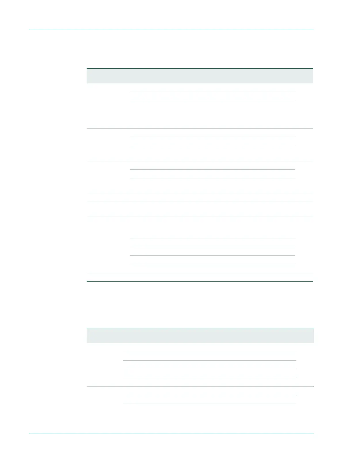
Table 201. UART FIFO Control Register (U0FCR - address 0x4000 8008, Write Only) bit
description
Bit Symbol Value Description Reset
value
0 FIFOEN FIFO Enable 0
0 UART FIFOs are disabled. Must not be used in the application.
1 Active high enable for both UART Rx and TX FIFOs and
U0FCR[7:1] access. This bit must be set for proper UART
operation. Any transition on this bit will automatically clear the
UART FIFOs.
1 RXFIFOR RX FIFO Reset 0
0 No impact on either of UART FIFOs.
1 Writing a logic 1 to U0FCR[1] will clear all bytes in UART Rx
FIFO, reset the pointer logic. This bit is self-clearing.
2 TXFIFOR TX FIFO Reset 0
0 No impact on either of UART FIFOs.
1 Writing a logic 1 to U0FCR[2] will clear all bytes in UART TX
FIFO, reset the pointer logic. This bit is self-clearing.
3 - Reserved 0
5:4 - Reserved, user software should not write ones to reserved bits.
The value read from a reserved bit is not defined.
-
7:6 RXTLVL RX Trigger Level. These two bits determine how many receiver
UART FIFO characters must be written before an interrupt is
activated.
0
0x0 Trigger level 0 (1 character or 0x01).
0x1 Trigger level 1 (4 characters or 0x04).
0x2 Trigger level 2 (8 characters or 0x08).
0x3 Trigger level 3 (14 characters or 0x0E).
31:8 - - Reserved -
Table 202. UART Line Control Register (U0LCR - address 0x4000 800C) bit description
Bit Symbol Value Description Reset
Value
1:0 WLS Word Length Select 0
0x0 5-bit character length.
0x1 6-bit character length.
0x2 7-bit character length.
0x3 8-bit character length.
2 SBS Stop Bit Select 0
0 1 stop bit.
1 2 stop bits (1.5 if U0LCR[1:0]=00).

 Loading...