UM10375 All information provided in this document is subject to legal disclaimers. © NXP B.V. 2011. All rights reserved.
User manual Rev. 3 — 14 June 2011 194 of 368
NXP Semiconductors
UM10375
Chapter 12: LPC13xx UART
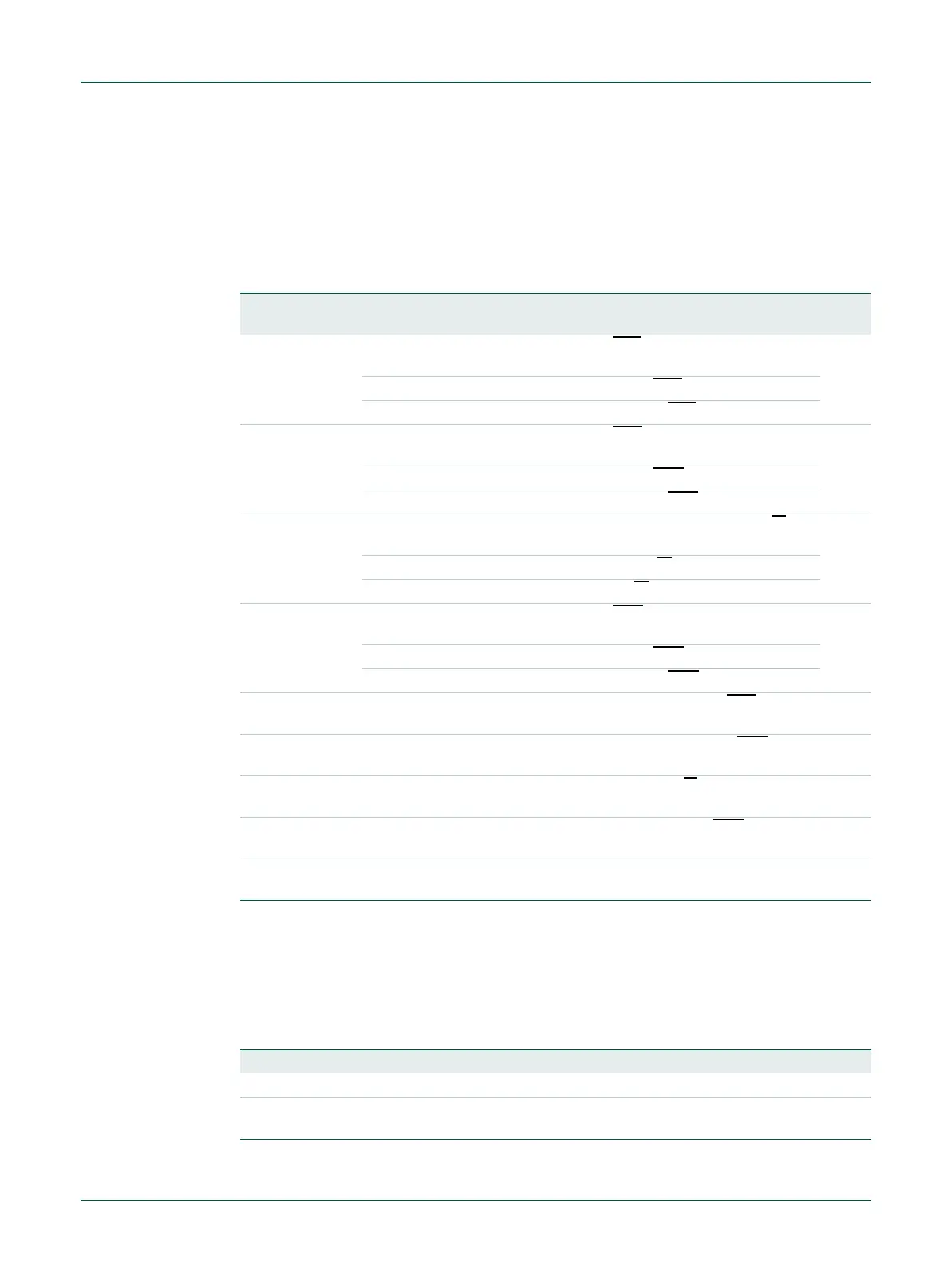
12.6.10 UART Modem Status Register
The U0MSR is a read-only register that provides status information on the modem input
signals. U0MSR[3:0] is cleared on U0MSR read. Note that modem signals have no direct
effect on the UART operation. They facilitate the software implementation of modem
signal operations.
12.6.11 UART Scratch Pad Register (U0SCR - 0x4000 801C)
The U0SCR has no effect on the UART operation. This register can be written and/or read
at user’s discretion. There is no provision in the interrupt interface that would indicate to
the host that a read or write of the U0SCR has occurred.
Table 206. UART Modem Status Register (U0MSR - address 0x4000 8018) bit description
Bit Symbol Value Description Reset
Value
0 DELTACTS Set upon state change of input CTS
. Cleared on a U0MSR
read.
0
0 No change detected on modem input CTS
.
1 State change detected on modem input CTS
.
1 DELTADSR Set upon state change of input DSR
. Cleared on a U0MSR
read.
0
0 No change detected on modem input DSR
.
1 State change detected on modem input DSR
.
2 TERI Trailing Edge RI. Set upon low to high transition of input RI
.
Cleared on a U0MSR read.
0
0 No change detected on modem input, RI
.
1 Low-to-high transition detected on RI
.
3 DELTADCD Set upon state change of input DCD
. Cleared on a U0MSR
read.
0
0 No change detected on modem input DCD
.
1 State change detected on modem input DCD
.
4 CTS Clear To Send State. Complement of input signal CTS
. This bit
is connected to U0MCR[1] in modem loopback mode.
0
5 DSR Data Set Ready State. Complement of input signal DSR
. This
bit is connected to U0MCR[0] in modem loopback mode.
0
6 RI Ring Indicator State. Complement of input RI
. This bit is
connected to U0MCR[2] in modem loopback mode.
0
7 DCD Data Carrier Detect State. Complement of input DCD
. This bit is
connected to U0MCR[3] in modem loopback mode.
0
31:
8
- - Reserved -
Table 207. UART Scratch Pad Register (U0SCR - address 0x4000 801C) bit description
Bit Symbol Description Reset Value
7:0 Pad A readable, writable byte. 0x00
31:
8
- Reserved -

 Loading...
