Operation
Defoliator
228 / 564
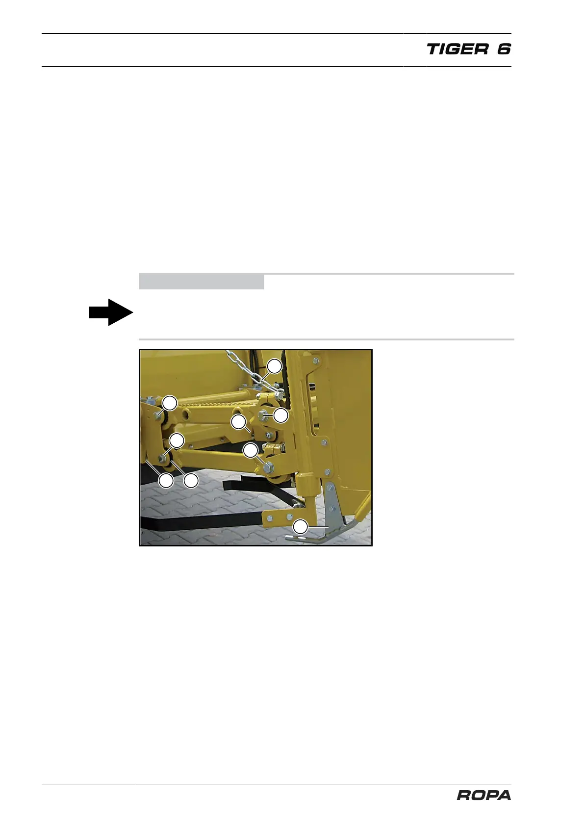
The 8 rubber suspension elements (6) must be set so that the skids (2) just touch the
ground straightly, but in no case rest on the ground with any weight.
For this purpose:
– Set the chain (3) shortened so far, that the skids (2) are about 15 cm above the
ground.
– Loosen four hexagonal bolts (4) each on the left/right.
– Check, if the base frame of the leaf sensor is touching the stop bolts (5) at the bot-
tom of the frontal rail of the defoliator housing. In case of need, the base frame
must be pushed back so far until it touches the stop bolts.
– Evenly strongly tighten four hexagonal bolts (4) on the left as well as on the right
side.
– Lengthen the chain (3) for so long and hang the chain so that it lightly sags, when
the leaf sensor is located so far down that it still securely senses the beet rows. In
this position, the leaf sensor may exclusively be suspended by the total of eight
rubber suspension elements (6), which are located at the pivots.
ADVICE
The electronic steering angle transmitter is located at the front, on the leaf sensor. The
settings of this component may not be changed in any case, because otherwise, the
sensor must be recalibrated.