Input Signal Jitter: <±500ns t o achieve oscillator lock, <±50ns to achieve system per-
formance
Programmable Phase Shift: ±5ns to 500ms with 5ns resolution
1PPS Output Specifications
Signal Type And Connector: TTL level (BNC)
Output Load Impedance: 50Ω
Rise Time to 90% of Level: <10ns
Programmable Pulse Width: 100ns to 900ms with 20ns resolution
Absolute Phase Error: ±50ns (1σ)
Programmable Phase Shift: ±5ns to 500ms with 5ns resolution
1PPS Input and Output: Viewing Signal State
To quickly view if the PPS inputs and outputs of this option card are currently enabled or dis-
abled, go to the option card’s Status Summary panel. For instructions, see: "Viewing an
Input/Output Signal State" on page349.
1PPS Input: Edit Window
To configure the settings for the 1PPS Input (also referred to as ‘Reference’), go to its Edit win-
dow. For instructions, see: "Configuring Option Card Inputs/Outputs" on page348.
The Web UI list entries for these cards are: 1PPS/Frequency BNC and 1PPS/Frequency RS-485.
The connector number is: J2 (Model 1204-03: RS-485 connector: Pins 5 and 6)
Note: SecureSync starts numbering I/O ports with 0 (only 1PPS and 10MHz out-
puts start at1, because of the built-in outputs).
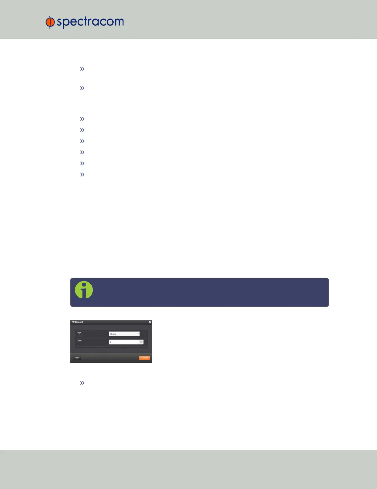
The Edit window allows the configuration of the following settings:
Edge: The operator can select either the rising or the falling edge as the input time ref-
erence (defines the on-time point of the signal).
SecureSync User Reference Guide 379
APPENDIX