Offset: It is possible to add an offset to the input signal (to account for cable delays),
with a resolution of 5ns and a positive or negative value of 500ms maximum.
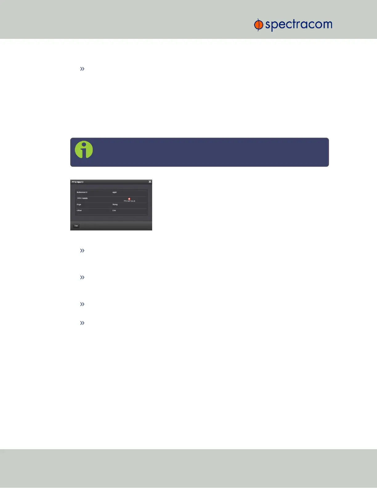
1PPS Input: Status Window
To view the current settings of the PPS Input (also referred to as ‘Reference’), go to its Status win-
dow. For instructions, see: "Verifying the Validity of an Input Signal" on page350.
The Web UI list entries for these cards are: 1PPS/Frequency BNC and 1PPS/Frequency RS-
485. The connector number is: J2 (Model 1204-03: RS-485 connector: Pins 5 and 6)
Note: SecureSync starts numbering I/O ports with 0 (only 1PPS and 10MHz out-
puts start at1, because of the built-in outputs).
The Status window displays the following settings:
Reference ID: Name used to represent this 1PPS input reference in the Reference Priority
table; see "Configuring Input Reference Priorities" on page163 for more information
on reference priority configuration.
1PPS Validity: Indicates “OK” (green) if the 1PPS input signal is present and valid. Indic-
ates “Not Valid” (orange) if the 1PPS input signal is either not present or is not con-
sidered valid.
Edge: Displays the selected Edge (rising of falling) of the 1PPS input that defines the on-
time point.
Offset: Displays the configured 1PPS offset values.
The 1PPS Input signal is analyzed and an absence of the signal triggers a “Not Valid” indic-
ation.
Frequency Input: Edit Window
To configure the settings for the Frequency Input (also referred to as ‘Reference’), go to its Edit
window. For instructions, see: "Configuring Option Card Inputs/Outputs" on page348.
The Web UI list entries for these cards are: 1PPS/Frequency BNC and 1PPS/Frequency RS-
485. The connector number is: J1 (BNC card); J1 (RS-485 card).
380 SecureSync User Reference Guide
APPENDIX