Note: Alarm Output 0 through Alarm Output 3 are reserved by SecureSync. In the
Web UI, numbering for alarm outputs for this option card will begin at Alarm 4,
which is available on the DB-9 output, while Alarms 5 and 6 are assigned to the
RJ-12 connector.
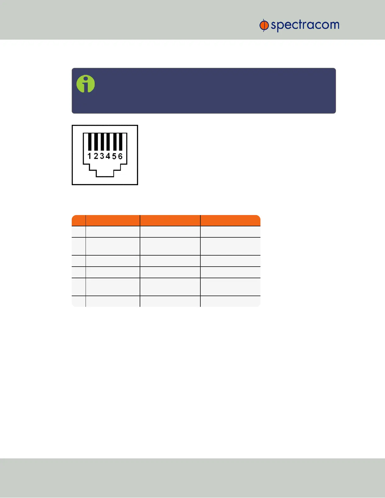
Figure 5-33: RJ-12 connector pin-out
Table 5-10:
RJ-12 pin assignments
PIN NOTES SIGNAL 938x SP360 Mapping
1 Cable Shield GROUND GROUND
2 5V = NORMAL
GROUND = ALARM
MAJOR ALARM RELAY MAJOR ALARM RELAY
3 RS-485 + Terminal Output 3+ + 1PPS
4 RS-485 - Terminal Output 3- - 1PPS
5 5V = NORMAL
GROUND = ALARM
MINOR ALARM RELAY MINOR ALARM RELAY
6 Cable Shield GROUND GROUND
CTCSS and Alarm Outputs: Viewing Signal States
To quickly view the current signal state of the 1204-14 Simulcast outputs, in the Web UI navigate
to the option card’s Status Summary panel. For instructions, see: "Viewing an Input/Output Sig-
nal State" on page349.
398 SecureSync User Reference Guide
APPENDIX