098-00028-000 Revision F – May, 2012 TimeProvider 5000 User’s Guide 37
Chapter 1 Overview
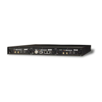
TimeProvider 5000 Connections
Figure 1-4 shows the EIA-232 male connector pin assignments for the serial port.
Figure 1-4. Serial Port Male Connector Pins
Table 1-5 describes the EIA-232 connector pin assignments for the serial port.
Output Connections
Programmable E1 Output Connections
Two of the traditional telecom synchronization coaxial ports (Port1 and Port2) on the
090-50311-01, 090-50312-01, and 090-50315-01 versions of the I/O module (Figure
1-5) are software configurable as E1 output ports, with the following signal types:
2.048 Mb/s (G.703/9)
2.048 MHz (G.703/13)
These ports can also be software configured as E1 inputs.
E1 Output Connections
Two of the four traditional telecom synchronization mini-BNC ports (Port3 and
Port4) on the 090-50311-01 version of the I/O module (Figure 1-5) are dedicated E1
output ports, with the following signal types:
2.048 Mb/s (G.703/9)
2.048 MHz (G.703/13)
Programmable T1 Output Connections
Two of the RJ-48C ports (I/O-1 and I/O-2) on the 090-50314-01 version of the I/O
module (Figure 1-6) are software configurable as T1 output ports, with the following
signal types:
Table 1-5. Serial Port Connector Pin Assignments
Signal Pin
TXD (Received Data) 2
RXD (Transmitted Data) 3
Ground 5
 Loading...