88 TimeProvider 5000 User’s Guide 098-00028-000 Revision F – May, 2012
Chapter 2 Installing
Making Ground and Power Connections
Testing Power Connections
To verify that the power connections to the TimeProvider 5000 are correct, follow
the steps in this section. The connections on the primary power module of the TP
5000 are referred to as Power A and Return A. The connections on the secondary
power module are referred to as Power B and Return B. Use a digital multimeter
(Fluke 77 or equivalent) to make the measurements.
1. Remove all fuses that supply power to the unit from the fuse panel.
2. Ensure that no IOC or IMC modules are installed in the unit.
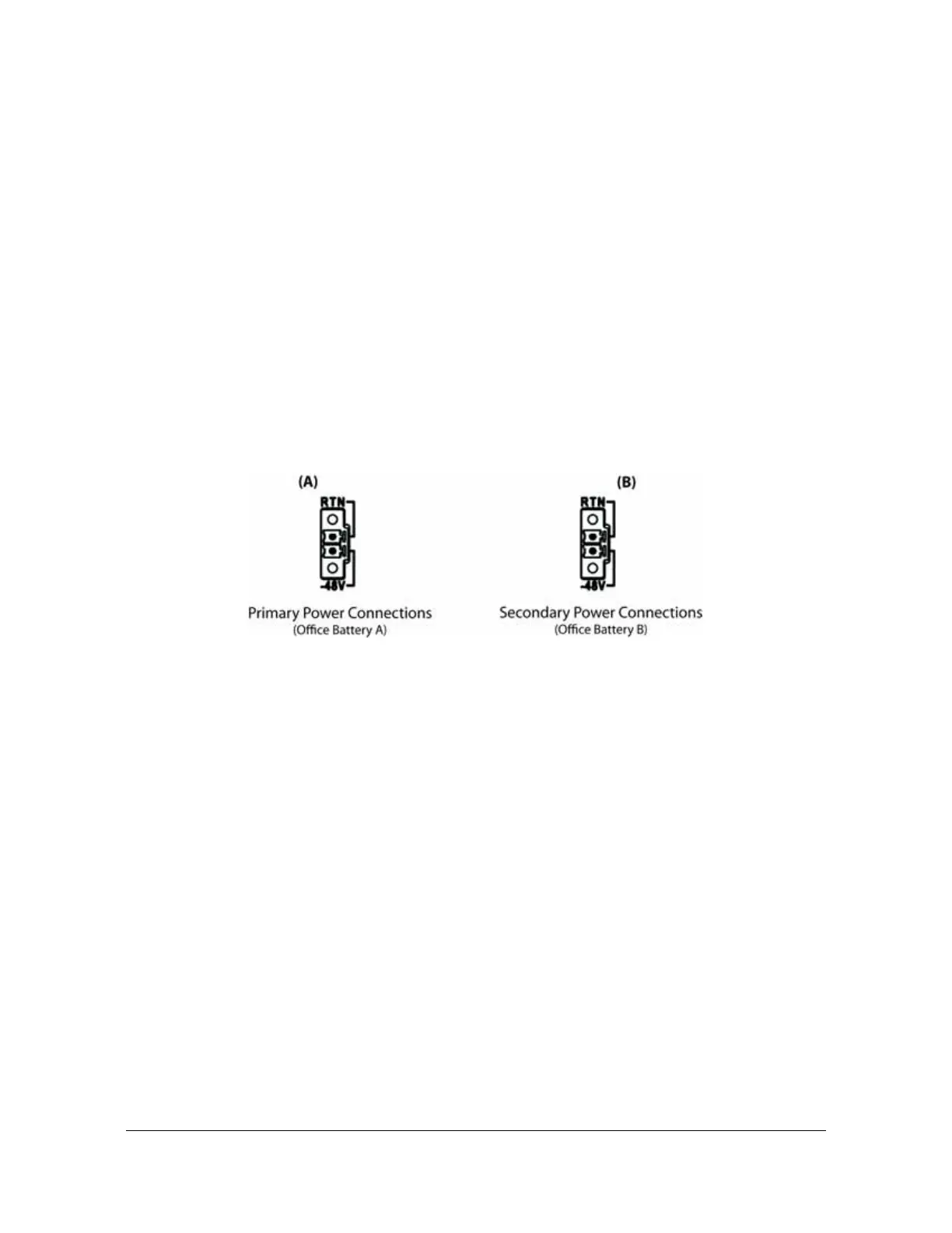
3. Disconnect the -48V battery leads from the unit’s power connector terminals. See
the primary and secondary power connections in Figure 2-34. Leave the Return
battery leads connected to the unit.
Figure 2-34. Power and Ground Connections on the TimeProvider 5000
4. At the chassis end of the battery leads, use the multimeter to measure the
voltage between the following test points:
Test Point Test Point Result
Battery A lead Battery B lead 0 V
Battery A lead Primary: Return A 0 V
Battery A lead Earth Ground 0 V
Battery B lead Secondary: Return B 0 V
Battery B lead Earth Ground 0 V
5. Reconnect the
–48V battery A and battery B leads to the –48V A and –48V B
terminal connectors.
6. Install the A fuse in the power source fuse panel.
7. Measure the voltage between the
–48V A and Return terminals on the primary
power module. The multimeter should indicate –42 VDC to –56 VDC.
8. Install the B fuse in the power source fuse panel.
9. Measure the voltage between the
–48V B and Return terminals on the secondary
power module. The multimeter should indicate –42 VDC to –56 VDC.
 Loading...