76 TimeProvider 5000 User’s Guide 098-00028-000 Revision F – May, 2012
Chapter 2 Installing
Signal Connections
To connect the expansion (UTI) ports on the 090-50311-01, 090-50312-01, and
090-50314-01 versions of the TP 5000 I/O card to an expansion shelf (TP E10 or
TP E30), use a custom cable. See Table 2-7 for pin-outs for the UTI expansion
RJ-45 connectors on the I/O card. See Table 2-8 for pin-outs for the EXP expansion
RJ-45 connectors on the expansion shelves. The custom cable should be built with
twisted-pair cable, CAT5 or better, with RJ-45 connectors and the custom mating
connector pinouts in Table 2-9.
Figure 2-20 shows the expansion connections for a TP 5000 with a single
expansion shelf, with redundant DTI connections from the expansion ports on the
IMC and I/O cards. Figure 2-21 shows the expansion connections for a TP 5000
with five expansion shelves. Redundant DTI connections for the IN1 and IN2 ports
on each expansion shelf are used to protect against various failure scenarios.
The expansion port from the IMC must always be used when using expansion
shelves to provide management messages via Ethernet. (The expansion ports on
the I/O card only provide DTI.)
Note: If using UTI ports from I/O modue 090-50311-01,
090-50312-01, or 090-50314-01, a custom cable must be used
between the I/O module and the expansion shelf. See
Table 2-9 for
details.
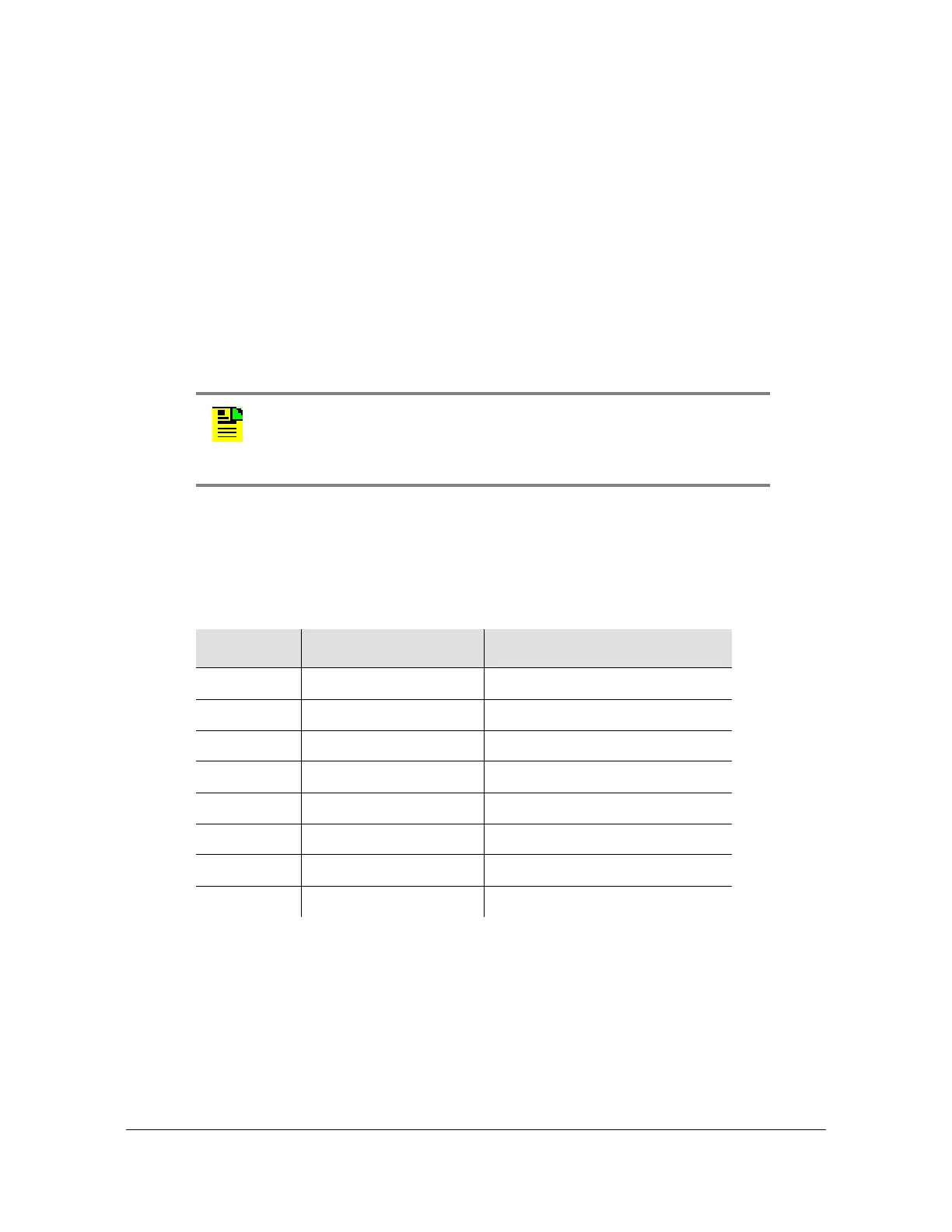
Table 2-6. Expansion Port (EXP) RJ-45 Connector Pin Assignments - I/O Card
Pin Signal
Comment
1 No connection
2 No connection
3 No connection
4 No connection
5 No connection
6 No connection
7 DTI+ DTI
8DTI DTI
 Loading...