098-00028-000 Revision F – May, 2012 TimeProvider 5000 User’s Guide 91
Chapter 2 Installing
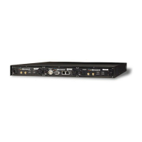
Applying Power to the TimeProvider 5000
Active
Indicates which IOC is
responsible for generating PTP,
Telecom, 10MHz, and 1PPS
outputs
ACT Off - Standby IOC or System Startup
Green - Active IOC
IOC Alarm
IOC module alarm/fault indicator
ALM Off - IOC operating normally
Amber - IOC operational Minor Alarm(s)
Red - IOC has Failed or has Major/Critical Alarm(s)
Flashing Green - Software starting up
Ethernet Port 1
ETH1 link/activity indicator
ETH1 Green - Link has been established
Flashing Green - Link activity
Off - Link has not been established
Ethernet Port 2
ETH2 port link/activity indicator
ETH2 Green - Link has been established
Flashing Green - Link activity
Off - Link has not been established
Local Oscillator State
Indicates the current mode of
operation of the LO servo
HOLD Off - Oscillator is operating in Locked mode
Amber - Oscillator is operating in Holdover or
Acquire modes
Flashing Amber - Oscillator is operating in Warm-up
mode
Expansion Port
LEDs on the RJ48 connector
EXP-1/
EXP-2
Left OFF - No DTI client detected
Left Amber - DTI client detected
Left Green - DTI client detected and ready
Table 2-16. Expansion Shelf LED Descriptions
LED Label Description
Power
Module Power Indicator
PWR Green - Power available
Off - Power not available
-48V A-Bus
A-Bus Battery Indicator
BT A Green - A-Bus power OK
Red - A-Bus power failed
-48V B-Bus
B-Bus Battery Indicator
BT B Green - B-Bus power OK
Red - B-Bus power failed
Alarm
Alarm/fault indicator
ALM Off - Operating normally
Amber - Operational Minor Alarm(s)
Red - Operational Major/Critical Alarm(s)
Ethernet Management Port
LEDs on the Ethernet connector
MGMT Green - Management communication is connected
Off - Management communication is not connected
Table 2-15. Module LED Descriptions (Continued)
LED Label Description
 Loading...