098-00028-000 Revision F – May, 2012 TimeProvider 5000 User’s Guide 87
Chapter 2 Installing
Making Ground and Power Connections
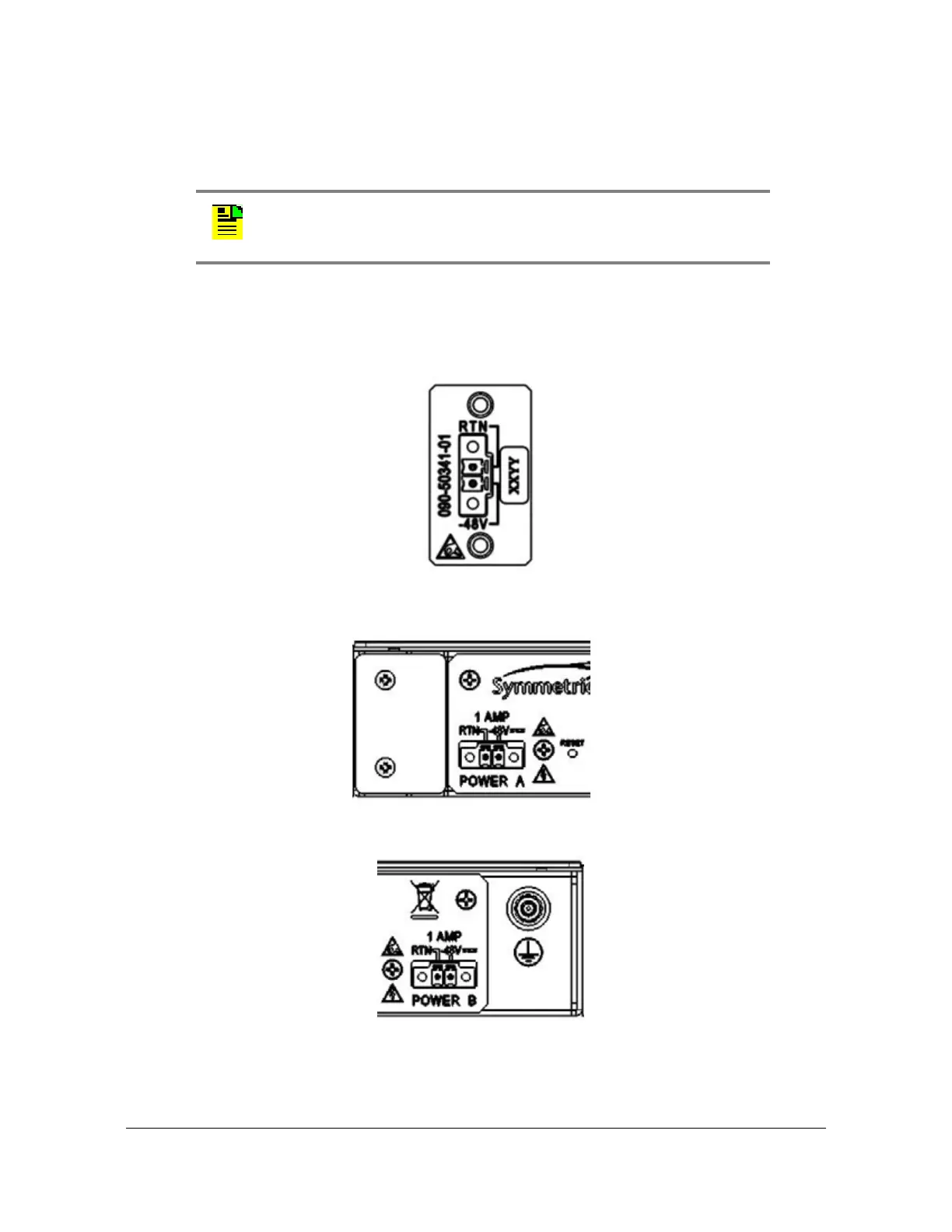
4. Using 1 mm² / 18 AWG (minimum) stranded wire, connect primary power to the
connectors per the polarity markings. Use the polarity markings of "-48V" and
"RTN" as a reference for the proper polarity connection..
5. Insert the connectors into the power connections in the chassis. See
Figure 2-31. Tighten screws in the connector
Figure 2-31. TimeProvider 5000 Power Connector
Figure 2-32. TP E10 and TP E30 - Power Connector A
Figure 2-33. TP E10 and TP E30 - Power Connector B
Note: The -48VDC power must be connected with the proper polarity.
The unit will not be damaged by reverse polarity, but the unit will not
operate if the polarity is reversed.
 Loading...