098-00028-000 Revision F – May, 2012 TimeProvider 5000 User’s Guide 83
Chapter 2 Installing
Connecting the GPS/GNSS Antenna
See Appendix B, Specifications and Factory Defaults for additional information
about the TOD signal.
Connecting the GPS/GNSS Antenna
The antenna connections for the TP 5000 are made at the IMC module connector
labeled GPS or GNSS. Allow at least one hour for the unit to track and lock to
GPS/GNSS.
5 GND RS422 GND
6 422_1_P 1PPS
7 422_2_N TOD time information
8 422_2_P TOD time information
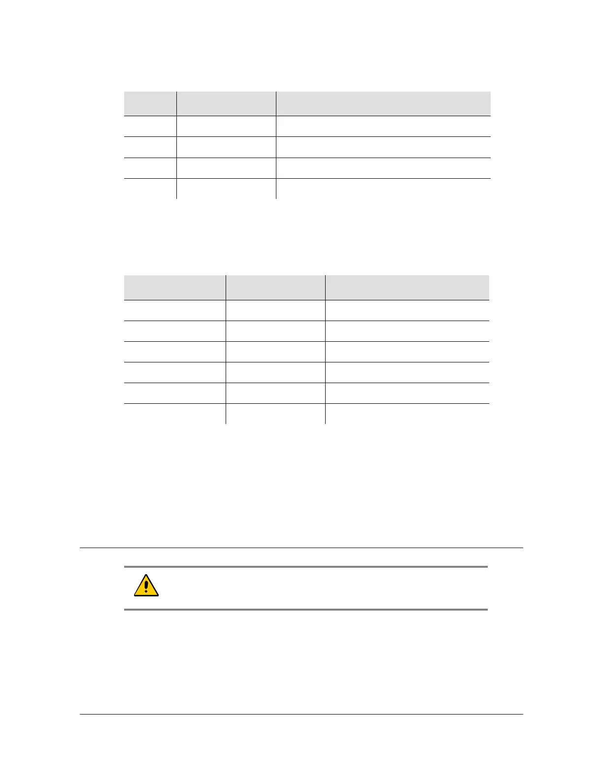
Table 2-13. TP E30 - Default Parameters for TOD Information Transmission
Pin Default Comment
Baud Rate 9600
Parity Check None
Start Bit 1 (low level)
Stop Bit 1 (high level)
Idle Frame High level
Data Bits 8
Caution: The GPS and GNSS cables should only be connected while
the unit is properly Earth grounded.
Table 2-12. TP E30 - 1PPS+TOD Port Pin-Outs - RJ45 Connector (Continued)
Pin Signal Comment
 Loading...