Appendix F, NetVanta Examples - EVC Maps
65K510DEP08-1A F-11
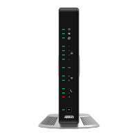
Figure F-1. E-Line Service - EVC per CE-VLAN
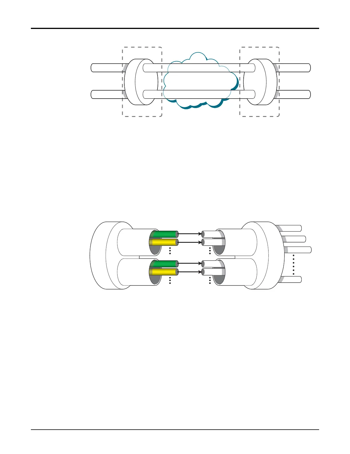
FigureF‐2providesamoredetailedviewofthemappingofthecustomerVLANsintothe
EVCsintheUNI‐to‐MENdirection.Forthisexample,bothEVCsresideonthesamebonding
group,andtheCoSforeachreceivedcustomerframeisinheritedfromtheP‐bitvalueof
the
outermostcustomerVLANtag.Thefollowingprovisioningappliesoneachsystem.
•EVC#1:MENPort=EFM‐Group1/0/1,S‐tag=101,CE‐VLAN‐IDPreservation=Enabled
•EVC#2:MENPort=EFM‐Group1/0/1,S‐tag=102,CE‐VLAN‐IDPreservation=Enabled
•EVCMap#1:UNI
=Ethernet1/0/1,CE‐VLAN‐ID=1,EVC=1,MEN‐Pri=Inherit
•EVCMap#2:UNI=Ethernet1/0/1,CE‐VLAN‐ID=2,EVC=2,MEN‐Pri=Inherit
Figure F-2. Detailed Mapping of Two Point-to-Point EVCs
Example #2: Two CE-VLANs Mapped to One EVC
FigureF‐3illustratesanexampleoftwocustomerVLANsthatingressthenetworkelementon
acommonUNIportandmaptoacommonEVC.CustomerVLANs1and2aremappedtoan
EVCwithSVID101.
UNI
CE VLAN 1
CE VLAN 2
MEN
UNI
CE VLAN 1
CE VLAN 2
EVC #1, SVID = 101
EVC #2, SVID = 102
UNI
P-bit 6
P-bit 7
CE VLAN ID 1
P-bit 6
P-bit 7
CE VLAN ID 2
P-bit 7
P-bit 6
P-bit 7
EVC #2
VID 102
EVC #1
VID 101
Bonding
Group
Metro Ethernet
Network Interface
Customer
Interface
Link #1
Link #n
Link #2
Link #3
P-bit 6

 Loading...