R3765/67G Series Network Analyzer Operation Manual
5.5 Ripple Measurement in the Bandwidth
5-31
5.5 Ripple Measurement in the Bandwidth
Here explains how to measure the ripple in the bandwidth.
• 385MHz band-pass filter is used as DUT.
Setup (filter connection) (refer to sub-section 3.5.1) and preset (refer to sub-section
4.4.1).
Press [CH 2] to set the active channel to 2.
Set the center frequency and the span.
[CENTER] [3] [8] [5] [MHz]
[SPAN] [5] [0] [MHz]
Calibrate the frequency characteristic.
Remove DUT and connect the through adapter instead.
Normalize in this state.
[CAL] {NORMALIZE (THRU)}
Following the completion, return the connection to DUT (filter).
Set the measurement format to magnitude (log display) and adjust the scale.
[SCALE] {AUTO SCALE}
Specify a part (delta section).
Specify a delta section.
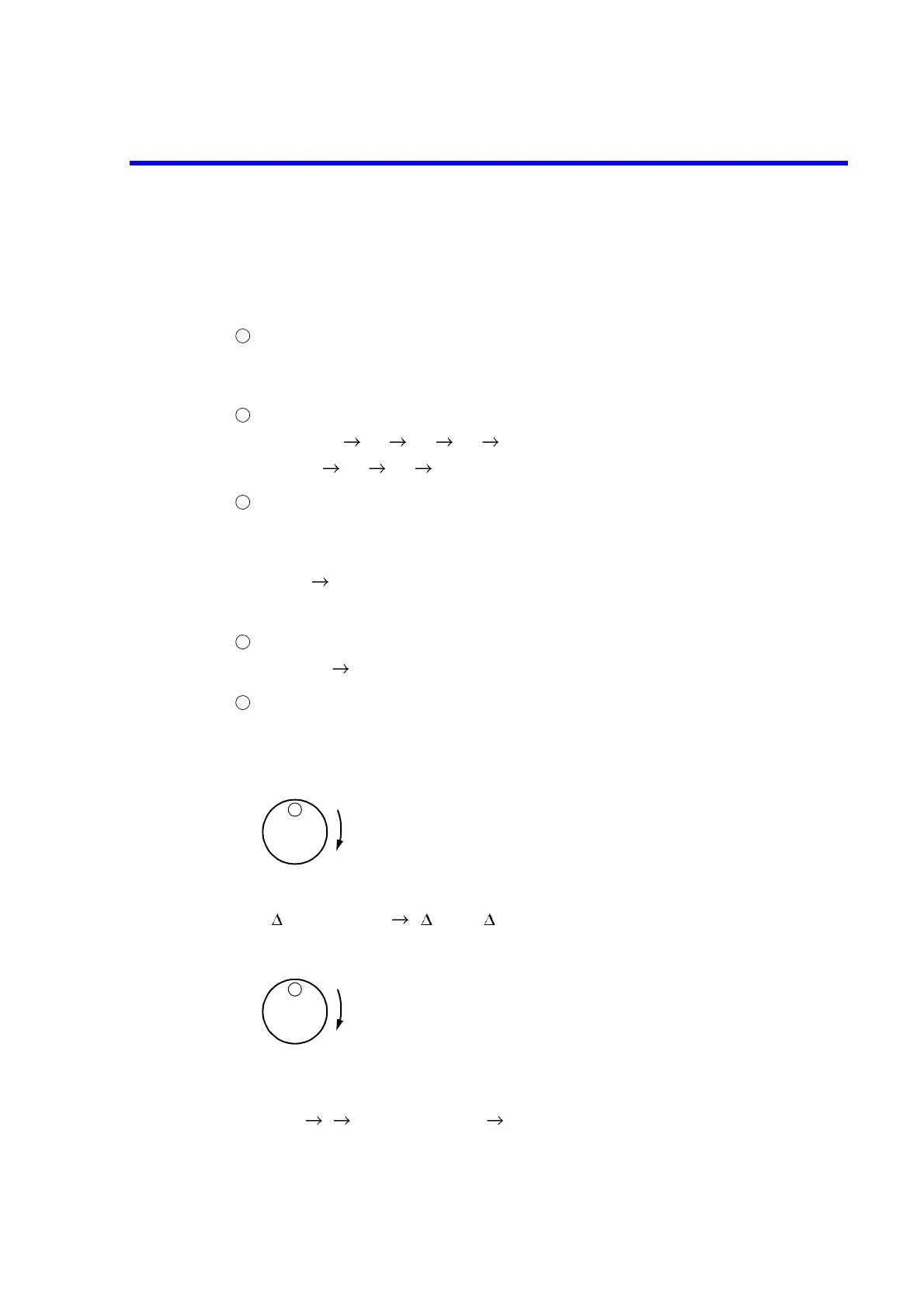
Move marker 1 with the data knob to one end of the specified section.
[MKR]
Set the reference marker to the position of marker 1.
{ MODE MENU} { REF = MKR}
Move marker 1 with the data knob to the other end of the specified section.
The area between the reference marker and marker 1 is the delta section.
Specify the delta section as the range of partial search.
[MKR ] {PART SRCH [ ]} {SET RANGE}
Make the partial search effective.
{PART SRCH ON/OFF}
1
2
3
4
5
Data knob
Data knob
 Loading...

