R3765/67G Series Network Analyzer Operation Manual
7.10 Software Fixture Function (OPT 71/72)
7-101
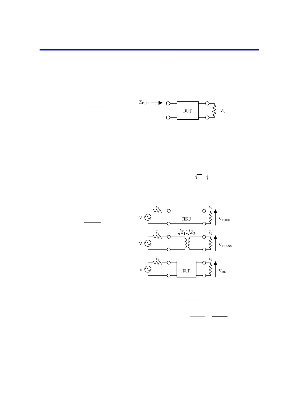
(1) Reflection parameter S
11
Where the device impedance seen from the input side (PORT 1) is Z
DUT
when the device
output side (PORT 2) is terminated with impedance Z
2
, S
11
can be calculated using the fol-
lowing expression.
Figure 7-14 Reflection Parameter
(2) Transmission parameter S
21
Where the signal source with Z
1
impedance and the load (receiving section) with Z
2
imped-
ance exists, S
21
can be calculated using the following expression according to the condi-
tions shown below.
• V
THRU
appears across the load if the signal source is directly connected to the load.
• V
TRANS
appears across the load when a transformer of is inserted between
the signal source and the load.
• V
DUT
appears across the load when a DUT is inserted between the signal source and
the load.
Figure 7-15 Transmission Parameter
In particular where Z
1
=Z
2
, Z
TRANS
=Z
THRU
, and .
On the contrary where Z
1
≠Z
2
, Z
TRANS
≠Z
THRU
, and .
Z
DUT
- Z
1
Z
DUT
+ Z
1
S
11
=
Z
1
:
Z
2
V
DUT
V
TRANS
S
21
=
V
DUT
V
TRAN
S
21
= =
V
DUT
V
THRU
V
DUT
V
TRANS
S
21
= ≠
V
DUT
V
THRU
 Loading...

