R3765/67G Series Network Analyzer Operation Manual
2.1 Front Panel Descriptions
2-10
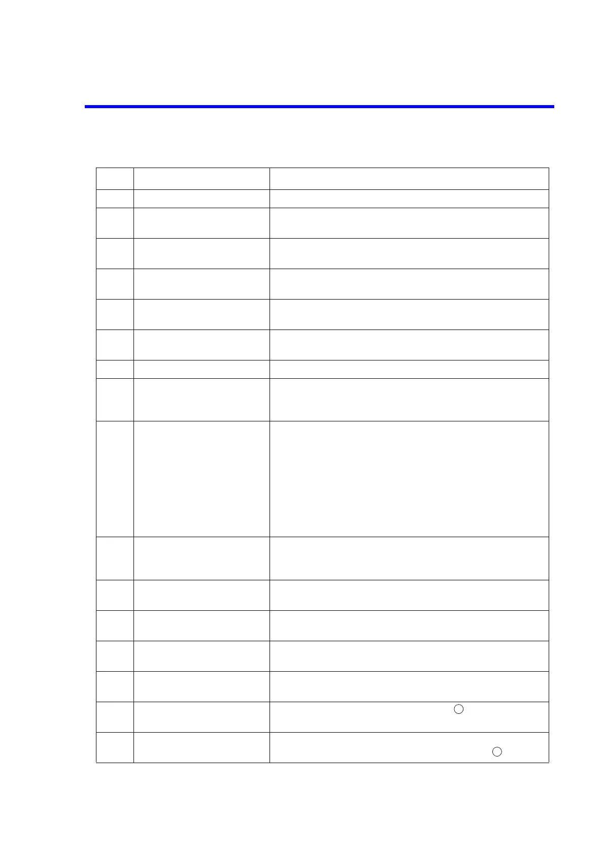
Table 2-5 Front-Panel Descriptions (R3765CG/67CG (OPT14))
No. Name Description
1 POWER switch Turns on or off the power supply of the R3765CG/67CG.
2 PORT 1 connector
TEST PORT 1
Measurement of PORT 1.
3 PORT 1 connector
TEST PORT 2
Measurement of PORT 2.
4 PORT 1 connector
TEST PORT 3
Measurement of PORT 3.
5 PORT 1 connector
TEST PORT 4
Measurement of PORT 4.
6 LCD display Displays measurement data, setting conditions and other
informations.
7 BACK LIGHT Selects the back light ON/OFF of LED display.
8 Floppy disk drive Stores a program and measurement data.
Three modes of storage capacity (DD: 720KB, HD: 1.2MB,
HD: 1.44MB).
9 ACTIVE CHANNEL block The ACTIVE CHANNEL block is used to select an active
channel between independently two measurement
channels.
Each channel has a sub-measurement screen which can be
selected by toggle.
Sub-measurement screen of CH1 : CH3
Sub-measurement screen of CH2 : CH4
After selecting, functions to be operated are effective to the
selected active channel.
10 RESPONSE block The RESPONSE block is used to set measurement
conditions of receiver section, data display and data
analysis.
11 STIMULUS block The STIMULUS block is used to set frequencies, level and
sweep conditions of signal source.
12 INSTRUMENT STATE
block
The INSTRUMENT STATE block is used set the system
functions which have no concern with the measurement.
13 GPIB block The GPIB block is used to set a GPIB and controller
functions.
14 ENTRY block The ENTRY block is used to input numeric data and to
perform a marker movement.
15 Soft key Selects the soft key menu described in in each function
block.
16 Soft key menu Displays each function menu.
To select a menu, use the soft key described in .
15
14
 Loading...

