R3765/67G Series Network Analyzer Operation Manual
5.1 Measurement of Transmission Characteristic (2 Trace Display)
5-6
5.1.2 Split Display
Here explains how to measure logarithmic magnitude and phase with simultaneous display of
channel 1 and 2.
• 880MHz band-pass filter is used as DUT.
Setup (refer to sub-section 3.5.1) and preset (refer to sub-section 4.4.1).
The setting of the R3765/67G series is as follows.
Change the input port of channel 1.
Note: OPT11 or OPT14 uses a different [MEAS] menu.
For more information, refer to the description on page 7-10.
Calibrate the frequency characteristic.
First, remove DUT and connect the through adapter instead.
Normalize in this state.
[CH 2] [CAL] {NORMALIZE (THRU)}
Following the completion, return the connection to DUT (filter).
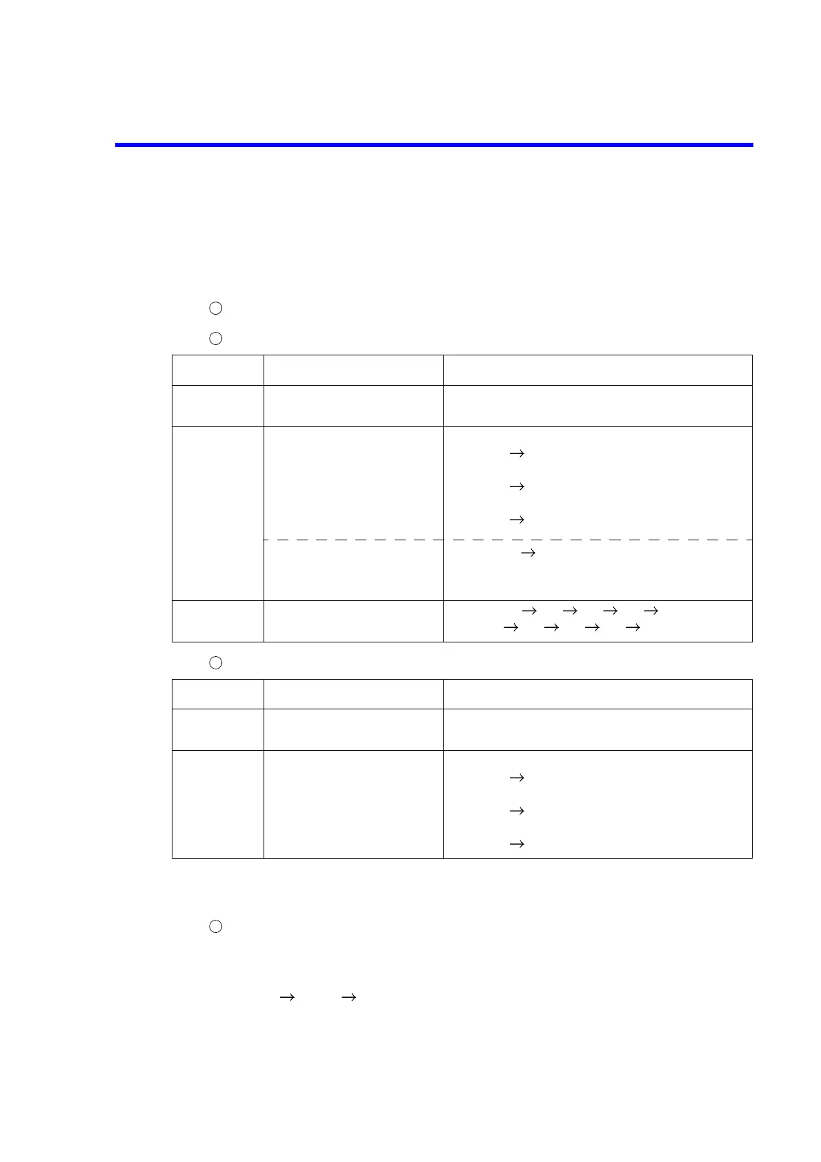
Block name Setting Key operation
ACTIVE
CHANNEL
Set the channel to 2. [CH 2]
RESPONSE Select the input port in the
receiver part.
Set the measurement
format to magnitude (log
display).
AG type :
[MEAS] {B/R} (Initial setup)
BG type :
[MEAS] {TRANSMISSION} (Initial setup)
CG type :
[MEAS] {S21 TRANS FWD} (Initial setup)
[FORMAT] {LOG MAG}
STIMULUS Center frequency 880MHz
Span frequency 100MHz
[CENTER] [8] [8] [0] [MHz]
[SPAN] [1] [0] [0] [MHz]
Block name Setting Key operation
ACTIVE
CHANNEL
Set the channel to 1. [CH 1]
RESPONSE Select the input port in the
receiver part.
AG type : Bridge is used.
[MEAS] {B/R}
BG type :
[MEAS] {TRANSMISSION}
CG type :
[MEAS] {S21 TRANS FWD}
1
2
3
4
 Loading...

