R3765/67G Series Network Analyzer Operation Manual
10.6 Load Match of Test Port
10-18
(2) Load match measurement of TEST PORT 2
Testing procedure
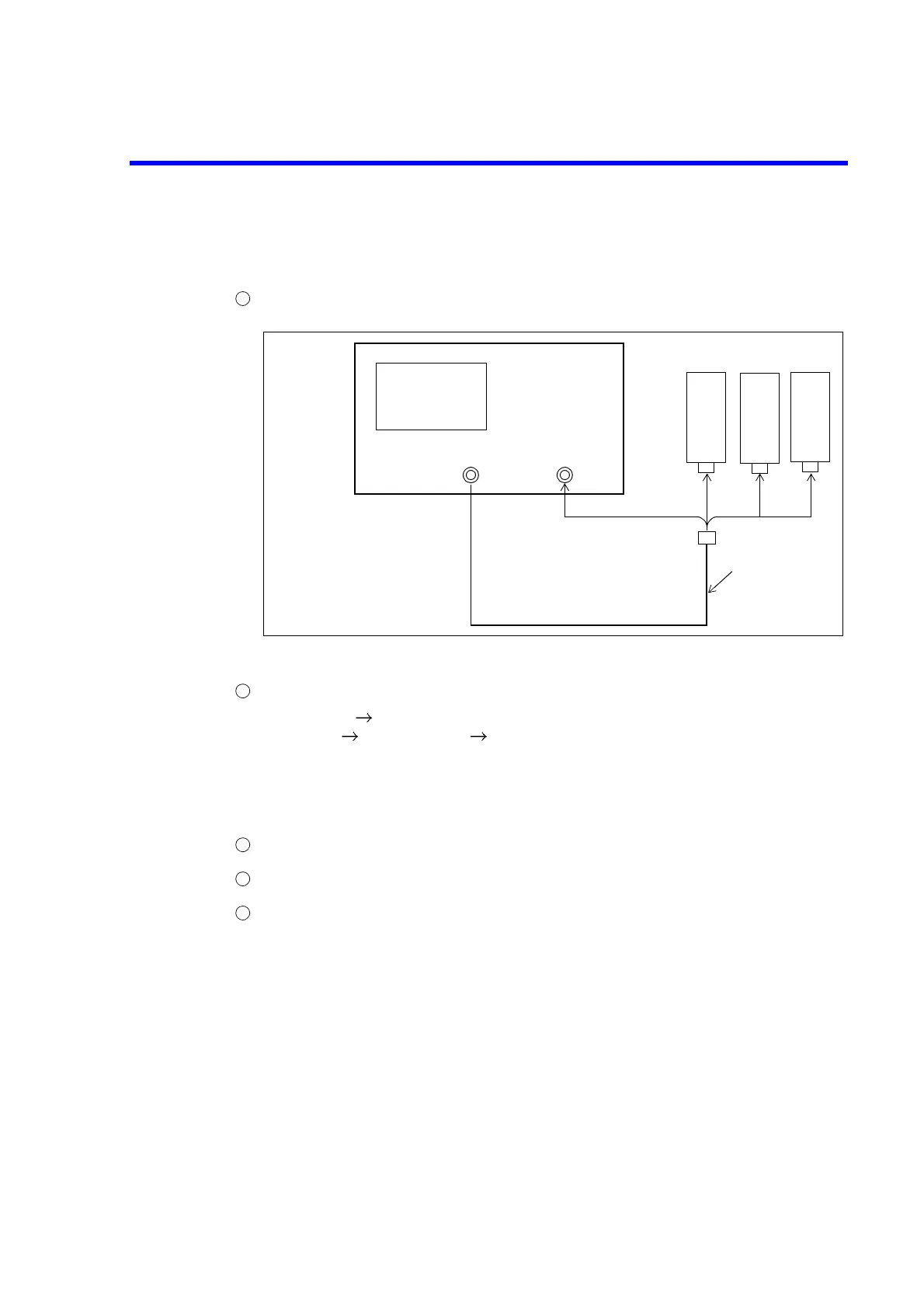
Setup the R3765CG/67CG as follows.
Figure 10-10 Load Match Measurement of TEST PORT 2 (R3765CG/67CG)
Perform 1 port full calibration
(a) [MEAS] {S11 REFL FWD}. (For OPT11/OPT14, {S11 (PORT 1)})
(b) [CAL] {CAL MENUS} {1 PORT FULL CAL}.
(c) Connect the open standard to the tip of RF cable and press {OPEN}.
(d) Connect the short standard to the tip of RF cable and press {SHORT}.
(e) Connect the load standard to the tip of RF cable and press {LOAD}.
(f) Press {DONE 1 PORT}.
Connect TEST PORT 2 of the R3765CG/67CG and the tip of RF cable.
Read the load match of TEST PORT 2 from trace data with the marker.
<Check> : TEST PORT 2 load match (in 23°C ± 5°C)
300kHz to 40MHz : -16dB or less
40MHz to 2.6GHz : -18dB or less
2.6GHz to 3.8GHz : -16dB or less
3.8GHz to 8.0GHz : -14dB or less (R3767CG only)
OPT 12
300kHz to 2.0GHz : -16dB or less
2.0GHz to 3.8GHz : -15dB or less
1
TEST PORT 1 TEST PORT 2
R3765CG/67CG
RF cable
OPEN
standard
SHORT
standard
LOAD
standard
2
3
4
5
 Loading...

