R3765/67G Series Network Analyzer Operation Manual
7.10 Software Fixture Function (OPT 71/72)
7-102
(Reference)
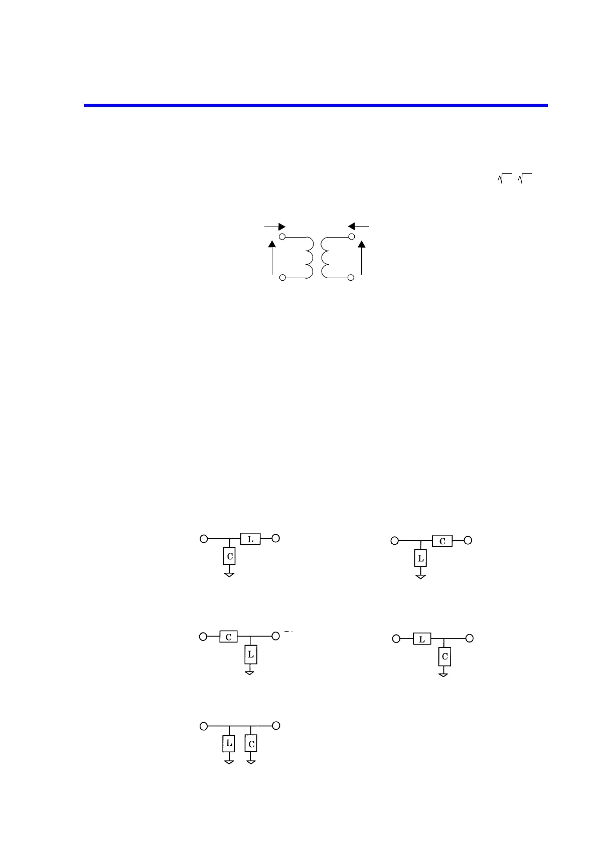
A transformer with a turn ratio of n
1
to n
2
has the voltages and currents shown in Figure 7-
16 Transformer. The S parameters are as shown below when a transformer of is
normalized to Z
1
and Z
2
:
S
11
= S
22
= 0, and S
21
= S
12
= 1.
Figure 7-16 Transformer
7.10.2.3 Matching Circuit Function
The matching circuit function is used to measure the characteristics of a DUT, assuming that an
arbitrary matching circuit is attached to the measurement port.
There are two setting methods for the matching circuit as shown below.
(1) Setting using the combination of a capacitor and an inductor
Arbitrary values can be set to capacitance C and inductance L.
In addition, the conductance component G of a capacitor and the resistance component R
of an inductor can be set.
There are five matching circuit models as a setting with C and L.
Z
1
: Z
2
I
1
V
1
n
1
: n
2
I
2
V
2
V
1
: V
2
= n
1
: n
2
I
1
: I
2
= (1/n
1
) : (1/n
2
)
• parallel C-series L (C(P)-L(S)-D)
• series C-parallel L (C(S)-L(P)-D)
• parallel L-parallel C (L(P)-C(P)-D)
DUT
TEST PORT
TEST PORT
DUT
TEST PORT
DUT
• parallel L-series C (L(P)-C(S)-D)
• series L-parallel C (L(S)-C(P)-D)
DUT
TEST PORT
TEST PORT
DUT
 Loading...

