R3765/67G Series Network Analyzer Operation Manual
10.9 Dynamic Level Accuracy
10-63
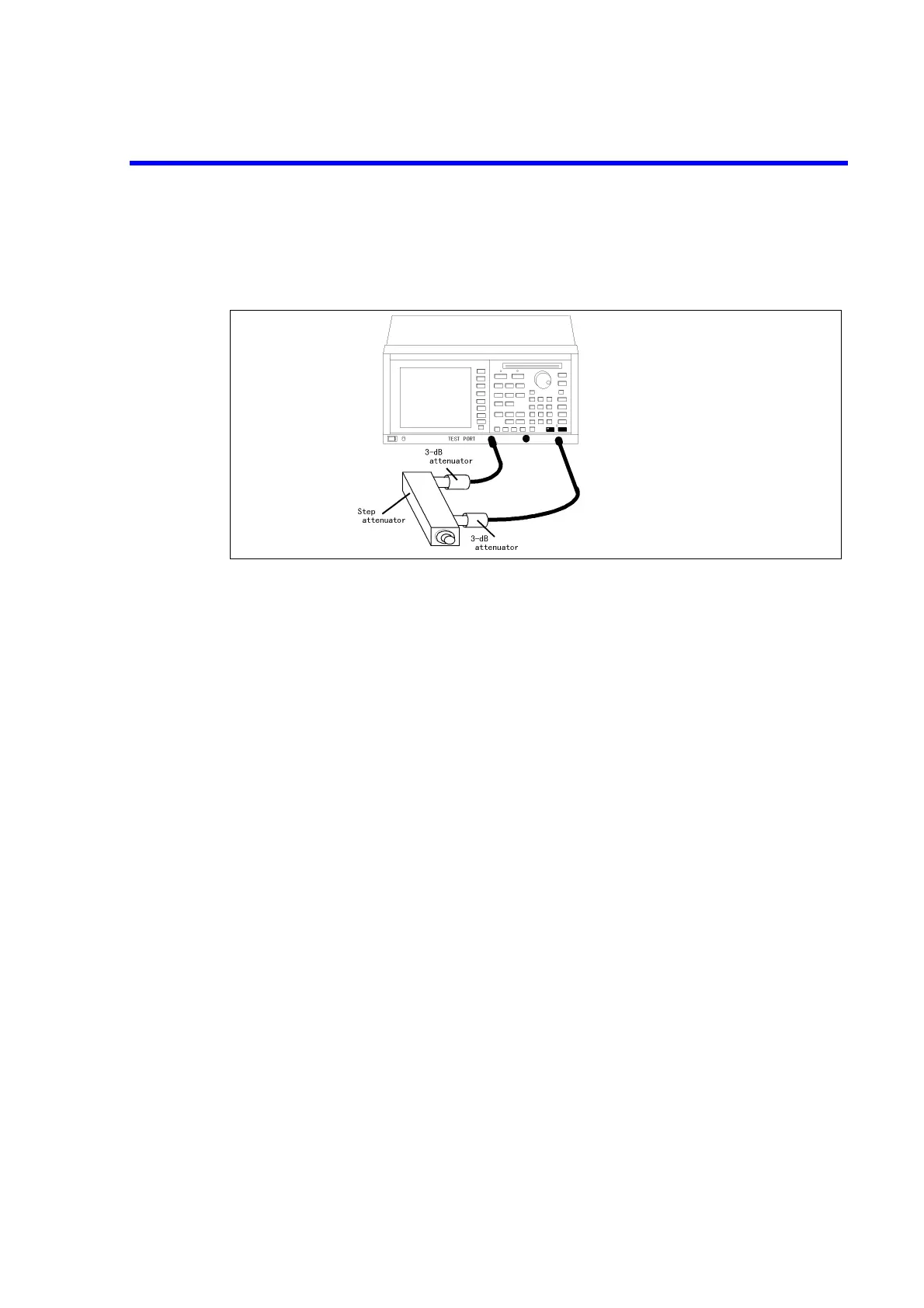
10.9.4.3.3 TEST PORT 3 Measurement for Dynamic Level Accuracy
(1) Connect two 3-dB attenuators and step attenuator using the RF cables between TEST
PORT 2 and TEST PORT 3 shown in Figure 10-36.
Figure 10-36 Connections for TEST PORT 3 Measurement
for Dynamic Level Accuracy
(2) Press [MEAS] and {S32 (P2
→
P3)}.
• Dynamic level accuracy at 50 MHz
(3) Press [CENTER], [5], [0] and [MHz] to set the center frequency to 50 MHz.
(4) Press [SPAN], [0] and [x1] to set the span to 0 MHz.
(5) Press [AVG], {IF RBW}, [1], [0], [0] and [x1] to set the RBW to 100 Hz.
(6) Press [MKR] to set the marker on.
(7) Press [MENU], {POWER}, [1], [0] and [x1] to set the output level to 10 dBm.
Set a value as shown below according to the options used.
OPT 10+OPT 11 or OPT 14: 5 dBm
OPT 10+OPT 13: -1 dBm
OPT 13: 4 dBm
(8) Set the step attenuator to 20 dB.
(9) Press [CAL] and {NORMALIZE (THRU)} to do normalization.
(10) Set the step attenuator to 10 dB.
(11) Read out the marker level.
(12) Repeat steps (10) and (11) on each set level listed on Table 10-5.
2
TEST PORT 3
* Connect the 50Ω to 75Ω
conversion adapter to
TESTPORT 1 and 2 for
OPT 13.
Note that the 3 dB fixed
attenuator is not required.
 Loading...

