R3765/67G Series Network Analyzer Operation Manual
7.6 Marker Function
7-68
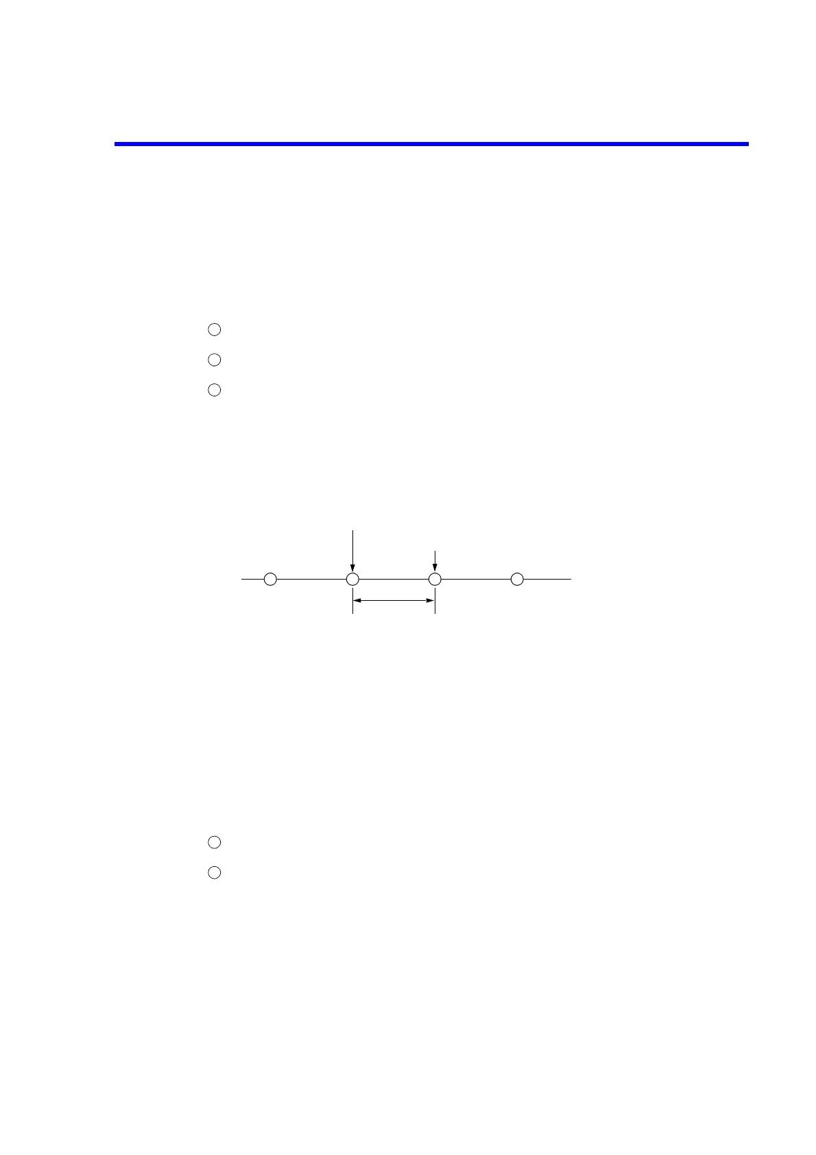
7.6.3 Interpolation between Measurement Points
The marker can be assigned to either one mode that sets markers and reads data of each marker
by interpolating linearly between measurement points and another mode that sets markers to
only actual measurement points.
The Setting and the Explanation
Press the [MKR] to call the marker menu. (Refer to section A.4.)
Press the {MARKER MODE MENU} to call the marker mode menu.
Interpolation between measurement points is selected by {MKR CMP/UNCMP}.
CMP : Interpolation (compensation) ON
UNCMP : Interpolation (compensation) OFF
When the sweep type is set to USER SWEEP/PROG SWEEP, even if CMP is selected,
the interpolation possibly don’t work depending on the number of set points.
7.6.4 Displaying Marker Read out Value
The marker value displayed on the screen always indicates the active marker. To display more
than that marker, use the marker list function to list all set markers at a time.
The marker list has two modes: in one mode, the marker list overlaps the waveform screen and
in the other mode, the screen is split into two, and the waveform and marker list are displayed
separately.
The Setting and the Explanation
Press the [MKR] to call the marker menu. (Refer to section A.4.)
Press the {MKR LIST ON/OFF} to select ON/OFF of the marker list display.
{SPLIT LIST ON/OFF} : Toggles the split display mode between ON and OFF.
When ON is set, the marker list is displayed on the split
screen.
When OFF is set, the marker list overlaps the waveform
screen.
This setting is commonly used for all channels.
1
2
3
Measurement point (n + 1)
Measurement point (n)
Measurement point interval
1
2
 Loading...

