R3765/67G Series Network Analyzer Operation Manual
7.10 Software Fixture Function (OPT 71/72)
7-119
7.10.3 Measurement Example
The measurement example of a filter with balanced input and balanced output (4-port device) is
given below.
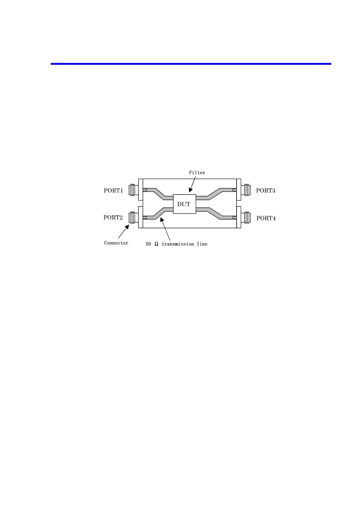
The filter is measured in a condition where it is installed on the jig as shown in Figure 7-17. PORT
1 and PORT 2 are balanced input and PORT 3 and PORT 4 are balanced output.
This measurement needs OPT 14 and OPT 71.
7.10.3.1 Measurement Jig
Figure 7-17 Measurement Jig for Balanced Input and Balanced Output Filter
7.10.3.2 Operation Procedure
The following steps (1) through (4) give explanations of basic settings for the software fixture
function.
The step (5) gives an explanation of the execution (measurement) of the software fixture func-
tion.
(1) Performing calibration
Set the frequencies in accordance with the filter to CENTER 200 MHz and SPAN 300 MHz
to perform a 4-port calibration.
For more information on a calibration procedure, refer to Section 7.5.12, "4-Port Calibra-
tion."
When the R17050 Automatic Calibration Kit is used, refer to the R17050 operation manual.
Electrical lengths of each port
PORT 1 to DUT transmission line: 70 psec
PORT 2 to DUT transmission line: 70 psec
PORT 3 to DUT transmission line: 135 psec
PORT 4 to DUT transmission line: 135 psec
 Loading...

