R3765/67G Series Network Analyzer Operation Manual
7.16 Communication with Peripheral Devices
7-159
7.16 Communication with Peripheral Devices
As standard, the R3765/67G series is equipped with the parallel I/O interface and RS-232 interface
as well as the GPIB interface. With these interfaces, it can communicate with peripherals.
• Parallel I/O : Used for communication with peripheral devices such as a handler.
• RS-232 : Used for output of screen hard copy or print from BASIC by connecting to the
printer. (Refer to section 7.15 and sub-section 7.16.2.)
7.16.1 Parallel I/O Port
(1) Outline
The parallel I/O port is the input/output port to communicate with a handler or peripherals.
Use always the shield cable for the connection.
The parallel I/O connector on the back panel is used for communication.
Figure 7-23 shows the internal pin assignment and signals of the connector.
These I/O port is controlled with ENTER and OUTPUT commands.
• Input/output port
There are two output ports and two input/output ports, as follows:
Port only for output : A port ; 8-bit width
B port ; 8-bit width
Input/output port : C port ; 4-bit width
D port ; 4-bit width
• Port C status output, port D status output
Shows the settings of the input of the input/output ports C and D. It is low when C or D
port is set to input, it is high when it is set to output.
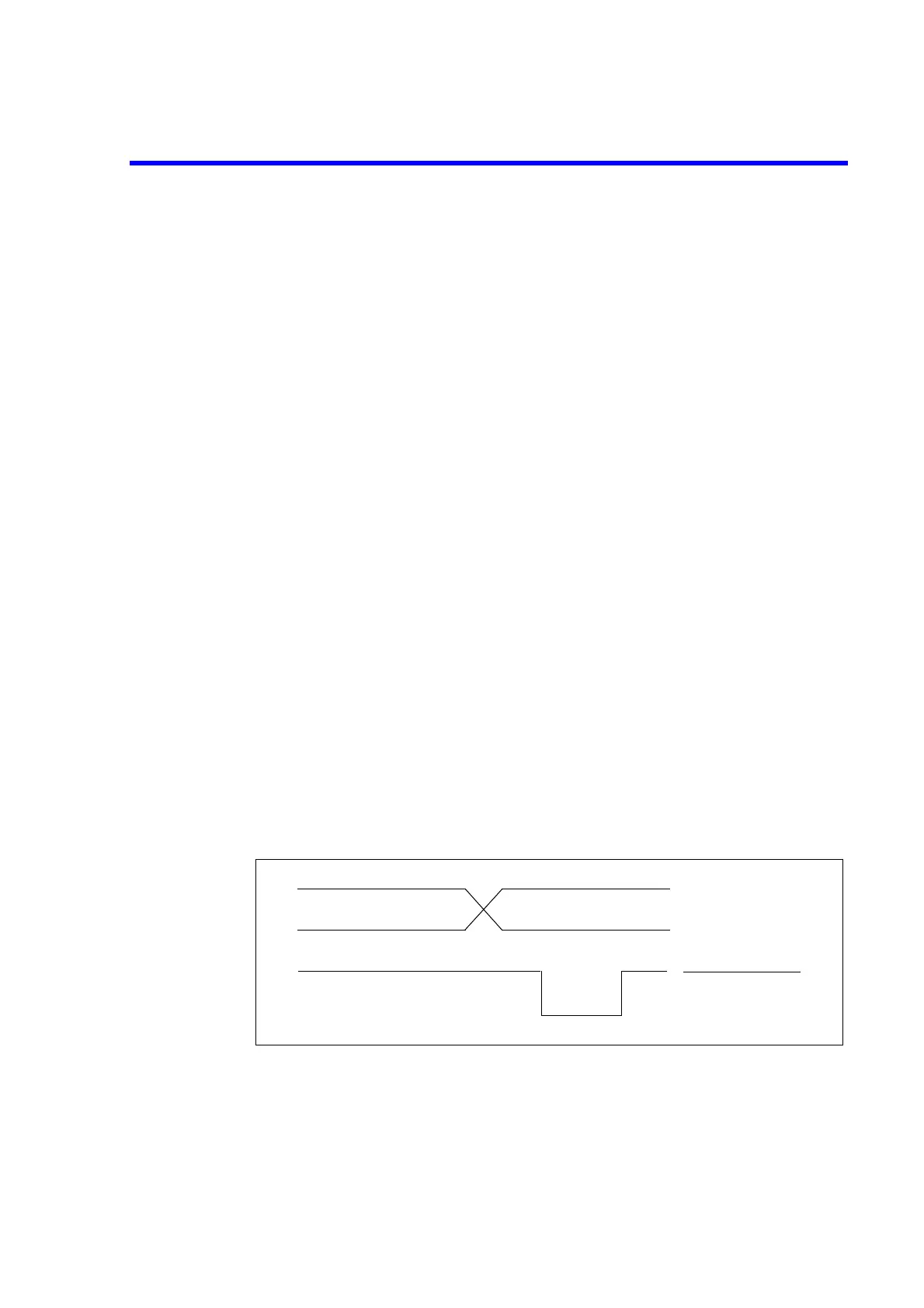
• Write strobe output for output port
By generating a negative pulse on the write strobe output, it shows a data is output to
some port.
Figure below shows the timing chart of the write strobe output and data output.
Figure 7-22 Timing Chart of WRITE STROBE
DATA OUTPUT
WRITE STROBE
 Loading...

