R3765/67G Series Network Analyzer Operation Manual
7.16 Communication with Peripheral Devices
7-160
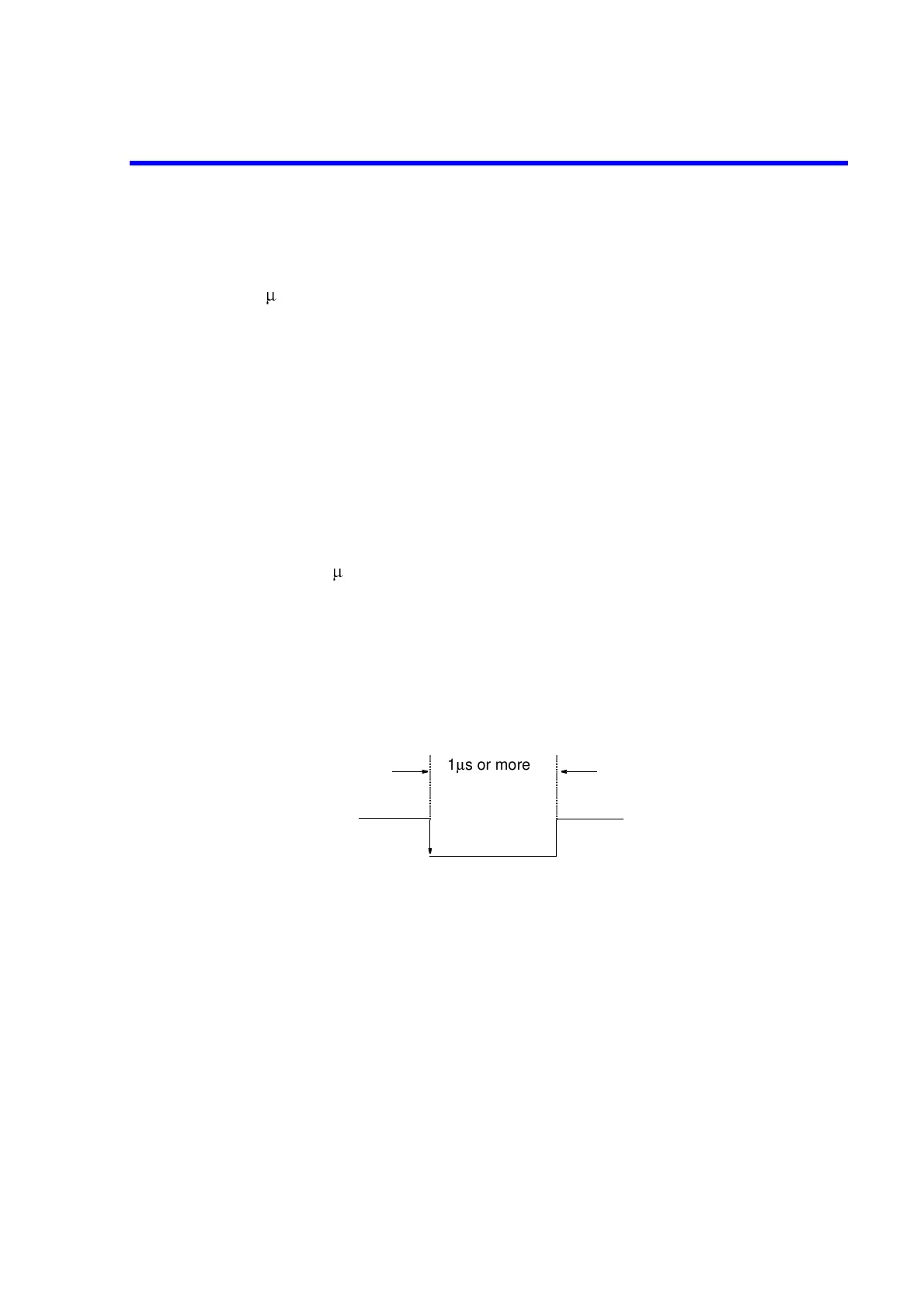
• INPUT 1
By entering a negative pulse on the INPUT 1, the OUTPUT 1 and 2 are set to LOW.
The pulse width of the input signal to be entered in the INPUT 1 should be more than
1s.
• OUTPUT 1 and 2
These two signal lines are the latch output terminals set to LOW when a negative
pulse is entered on the INPUT 1. It can be set to LOW or HIGH with the BASIC
command (OUTPUT).
• PASS/FAIL output
Generates LOW when the result of the limit test is PASS and HIGH when the result is
FAIL. This function is available only when the limit test function is ON.
• Write strobe output for PASS/FAIL output
When the limit test result is output to the PASS/FAIL output line, generates a negative
pulse.
• SWEEP END
When the R3765/67G series finishes the sweeping, generates a negative pulse with a
width of 10 s.
• +5V output
+5V output is provided for the external device. The maximum current to be supplied is
100mA. A protection element is equipped on this line to shut off the over-current.
• EXT TRIG input
By entering a negative pulse on this line, it is possible to trigger the sweep of
measurement. The pulse width should be at least 1
µ
s. The sweeping starts at the
trailing edge of the pulse. When this signal line is used, the trigger mode should be set
to external source.
1µs or more
 Loading...

