R3765/67G Series Network Analyzer Operation Manual
10.9 Dynamic Level Accuracy
10-65
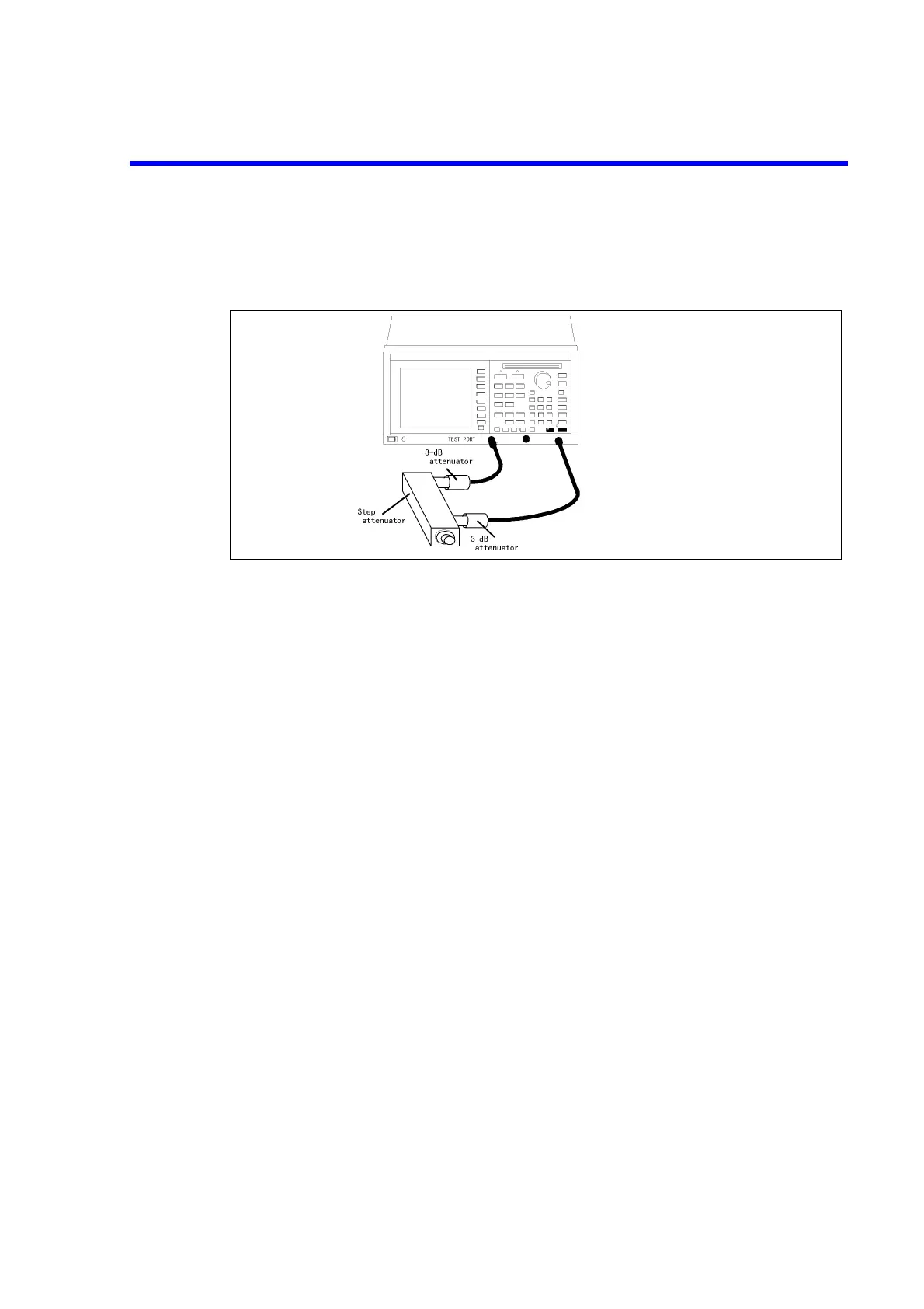
10.9.4.3.4 TEST PORT 4 Measurement for Dynamic Level Accuracy (For OPT 14)
(1) Connect two 3-dB attenuators and step attenuator using the RF cables between TEST
PORT 2 and TEST PORT 4 shown in Figure 10-37.
Figure 10-37 Connections for TEST PORT 4 Measurement
for Dynamic Level Accuracy
(2) Press [MEAS] and {S42 (P2
→
P4)}.
• Dynamic level accuracy at 50 MHz
(3) Press [CENTER], [5], [0] and [MHz] to set the center frequency to 50 MHz.
(4) Press [SPAN], [0] and [x1] to set the span to 0 MHz.
(5) Press [AVG], {IF RBW}, [1], [0], [0] and [x1] to set the RBW to 100 Hz.
(6) Press [MKR] to set the marker on.
(7) Press [MENU], {POWER}, [1], [0] and [x1] to set the output level to 10 dBm.
(8) Set the step attenuator to 20 dB.
(9) Press [CAL] and {NORMALIZE (THRU)} to do normalization.
(10) Set the step attenuator to 10 dB.
(11) Read out the marker level.
(12) Repeat steps (10) and (11) on each set level listed on Table 10-5.
(13) For each set level, calculate the dynamic level error using the following formula:
(dynamic level error) = (measured value) - (Offset value)
NOTE: The offset value is a attenuator error at the reference point.
(Offset value)=(calibration factor of the attenuator at the reference point)-(calibration
factor of the attenuator at the set level)
2
TEST PORT 3
 Loading...

