R3765/67G Series Network Analyzer Operation Manual
7.6 Marker Function
7-78
Search reference menu
Selects the reference point when analyzing filters (Note 1).
{ACTIVE MARKER} : Makes the active marker the level reference point.
{MAXIMUM VALUE} : Makes the minimum loss point the level reference point.
{REFERENCE LINE} : Makes the reference line the level reference point (Note 2).
Note 1: Each search reference (which is composed of the stimulus axis and the level axis) specified
by the search reference menu is as follows:
MAX : Minimum loss point/MIN : Maximum loss point/Active Mkr : Active marker/
Ref Line : Reference line
For example, when MAX reference has been selected for a band pass filter analysis,
the search reference point on the stimulus axis is the MAX (the minimum loss point);
the search reference point on the level axis is the MAX (the minimum loss point).
Note 2: The Reference Line reference can be selected only when the FORMAT is specified as LOG
MAG, LOG MAG&PHASE or LOG MAG&DELAY.
<Examples of the result of filter analysis>
Q factor is calculated from a bandwidth B.W’ where data is 3dB off a minimum loss
value of the measured data, and the center frequency C.F’ in the bandwidth B.W’.
C.F’
Q =
B.W’
Shaping factor is calculated from a bandwidth B.W’ where data is 3dB off minimum
loss value of the measured data, and a bandwidth B.W’’ where data is 60dB off the
minimum loss value.
B.W
’’
S.F =
B.W’
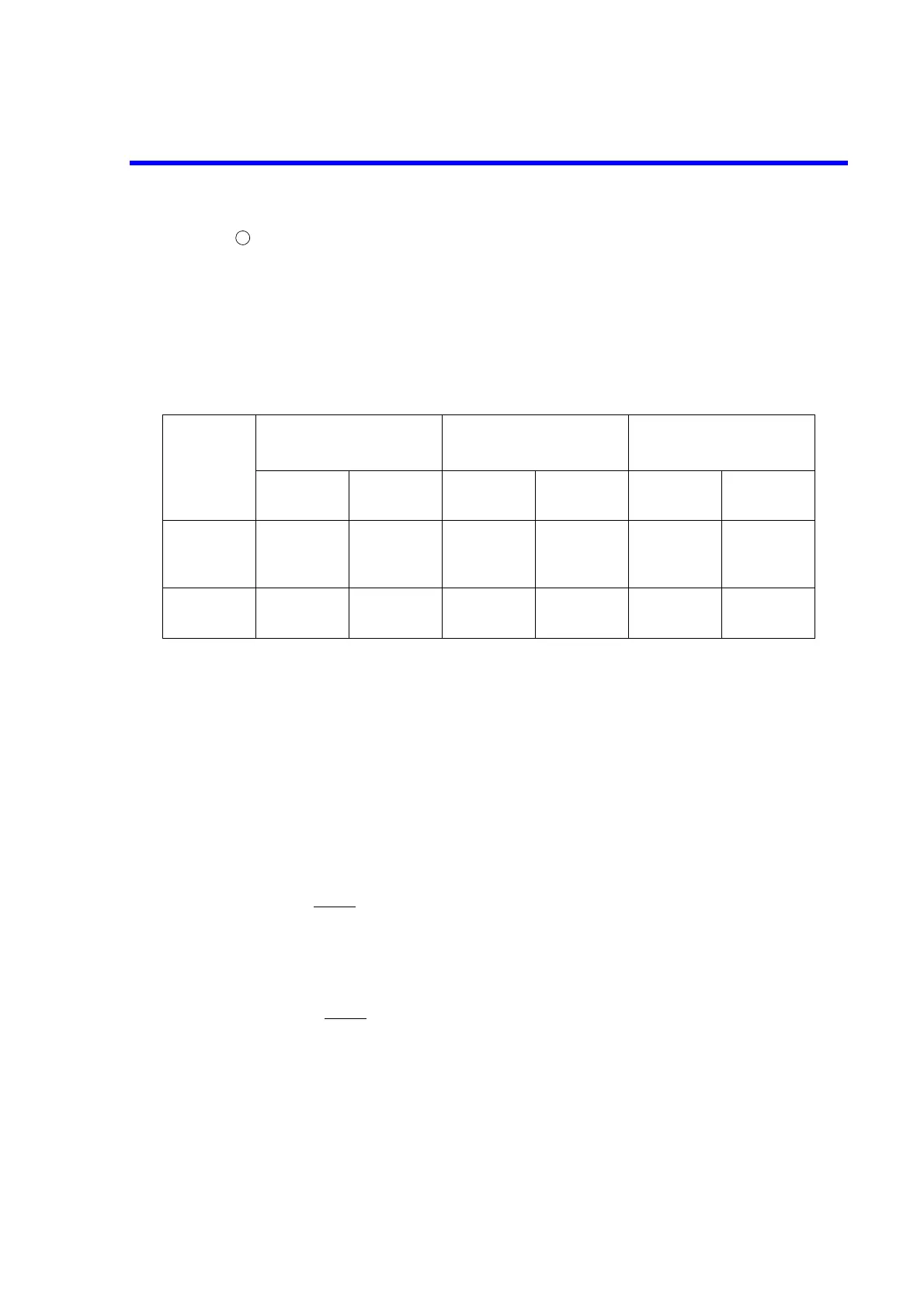
MAX reference Active marker reference
Reference line
reference
Stimulus
axis
Level axis Stimulus
axis
Level axis Stimulus
axis
Level axis
Band
pass filter
analysis
MAX MAX Active Mkr Active Mkr MAX Ref Line
Notch filter
analysis
MIN MAX MIN Active Mkr MIN Ref Line
7
 Loading...

