R3765/67G Series Network Analyzer Operation Manual
7.16 Communication with Peripheral Devices
7-164
(b) INPUT 1 (external input)
The state of OUTPUT 1 can be observed by INPUT 1 using ENTER statement.
ENTER 34; (numeric variable)
If 1 is assigned to the numeric variable, OUTPUT 1 is ON (Low level: negative logic),
if 0, OUTPUT 1 is OFF (High level).
Example : 10 OUTPUT 36 ; 16
20 ENTER 34 ; A
30 IF A<> 1 THEN GOTO 20
40 OUTPUT 33 ; 1
By observing the state of OUTPUT 1, if OUTPUT 1 is set to ON, then 1 is output to the
port A.
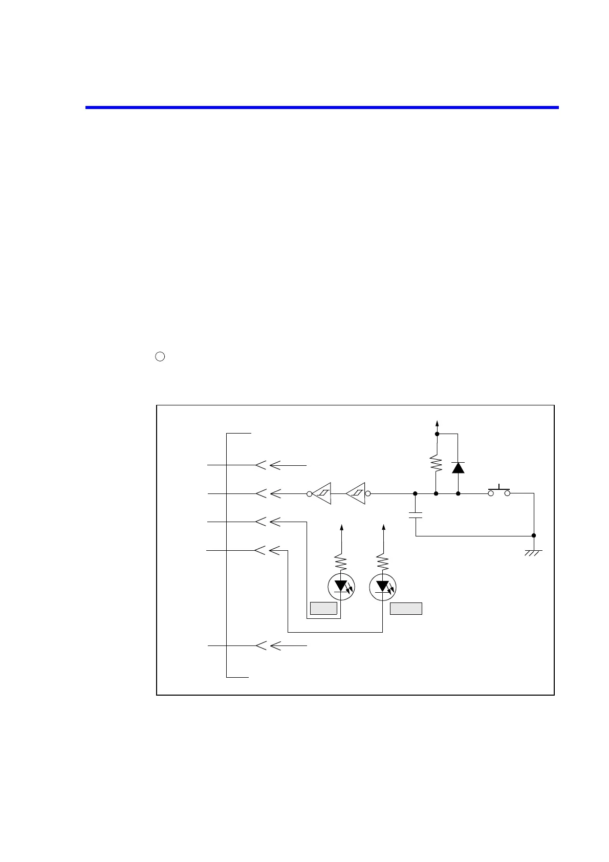
Examples of INPUT 1, OUTPUT 1 and OUTPUT 2
< When program is executed by trigger switch >
• Circuit example
1
PIO port
+5V
1
2
3
4
35
GND
Trigger SW
INPUT1
GND
OUTPUT1
+5V
OUTPUT2
+5V
+5V
+5V
MEAS
READY
GND
 Loading...
