R3765/67G Series Network Analyzer Operation Manual
7.16 Communication with Peripheral Devices
7-163
(b) Address and data range
• OUTPUT 33, 34, 37
OUTPUT ; 0 to 255 (8-bit)
• OUTPUT 35, 36
OUTPUT ; 0 to 15 (4-bit)
* The OUTPUT 35 concerns with the Set/Reset of Flip Flop.
• ENTER 35, 36
ENTER ; numeric variable (4-bit) (Data from 0 to 15 are assigned.)
• ENTER 37
ENTER 37 ; numeric variable (8-bit) (Data from 0 to 255 are assigned.)
(5) INPUT 1, OUTPUT 1 and OUTPUT 2 Terminals
By combining with the signal lines of INPUT 1, OUTPUT 1 and OUTPUT 2, convenient
functions are provided to easily control external devices.
The functions are; function which sets two latch outputs of OUTPUTs 1 and 2 to LOW by
pulse input to INPUT 1, and function which detects the state of OUTPUT 1 by INPUT 1.
Also, the state of OUTPUTs 1 and 2 can be controlled by OUTPUT command.
(a) Setting and Resetting of OUTPUT 1 and OUTPUT 2
The following four types are provided for set/reset as follows:
• Setting OUTPUT 1 : OUTPUT 35 ; 16
• Setting OUTPUT 2 : OUTPUT 35 ; 48
• Resetting OUTPUT 1 : OUTPUT 35 ; 80
• Resetting OUTPUT 2 : OUTPUT 35 ; 112
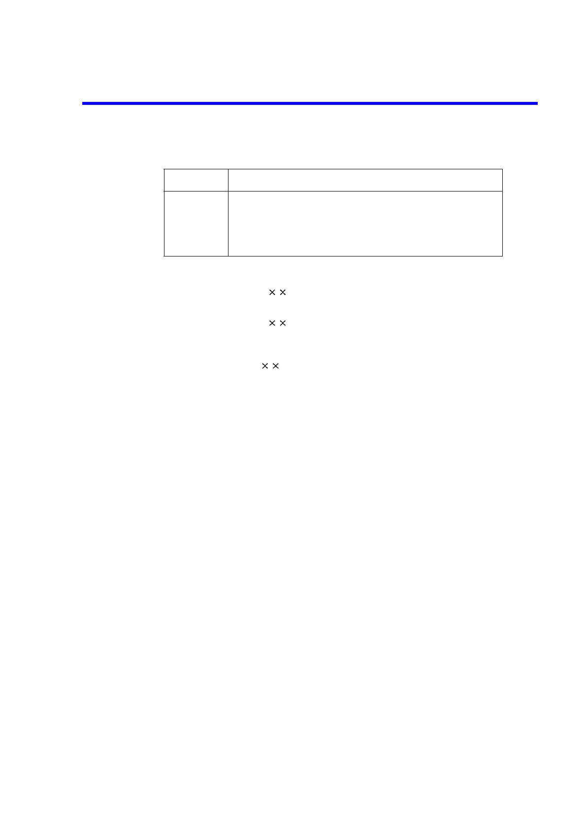
Address Port to be used
33
34
35
36
37
Port A (Output only: OUTPUT statement only)
Port B (Output only: OUTPUT statement only)
Port C (Input/output : ENTER, OUTPUT)
Port D (Input/output : ENTER, OUTPUT)
Port CD (Input/output : ENTER, OUTPUT)
 Loading...
