Name / value range / [default setting]
(P420.01)
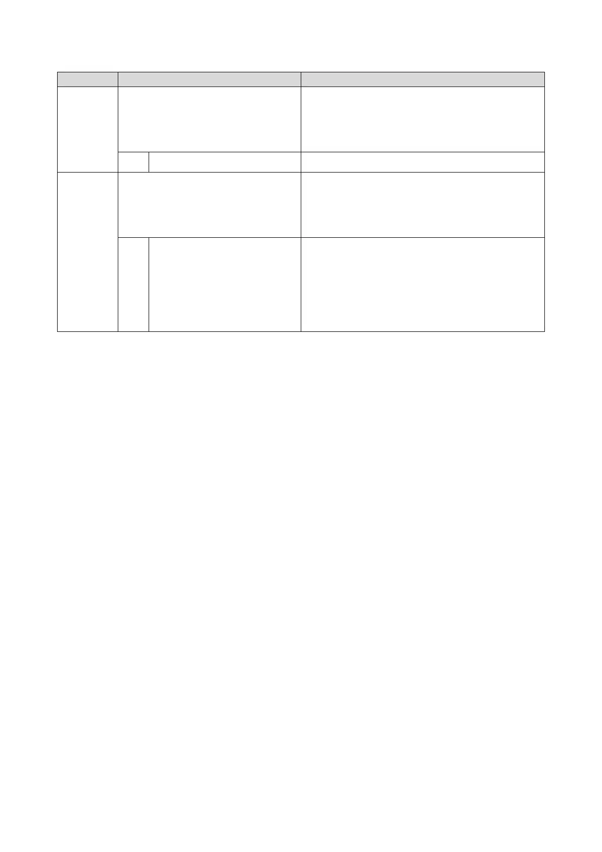
Digital outputs function: Relay
(Dig.out.function: Relay function)
•
For further possible settings, see parameter
0x2634:001 (P420.01).
429
Assignment of a trigger to the relay.
Trigger = FALSE: X9/NO-COM open and NC-COM closed.
Trigger = TRUE: X9/NO-COM closed and NC-COM open.
Notes:
•
An inversion set in 0x2635:001 (P421.01)is taken into consideration
51
Ready for operation
TRUE if inverter is ready for operation (no error active, no STO active
and DC-bus voltage ok). Otherwise FALSE.
(P420.02)
Digital outputs function: Digital output 1
(Dig.out.function: DO1 function)
•
For further possible settings, see parameter
0x2634:001 (P420.01).
429
Assignment of a trigger to digital output 1.
Trigger = FALSE: X3/DO1 set to LOW level.
Trigger = TRUE: X3/DO1 set to HIGH level.
Notes:
•
An inversion set in 0x2635:002 (P421.02) is taken into consideration
Trigger signal for releasing the holding brake (TRUE = release holding
brake).
Note!
If this trigger is assigned to the relay or a digital output, the deceleration
times set for the respective output are not effective (are internally set to
"0"). Only the deceleration time set in 0x2820:012 (P712.12) for closing
the holding brake influences in this case the time-dependent behaviour
of the output.
Holding brake control
302
All functional possible settings for controlling the inverter are described in the "
Flexible I/O
configuration
" chapter.
487