418 Upgrade and Maintenance Manual
TX150 S8 / TX200 S7
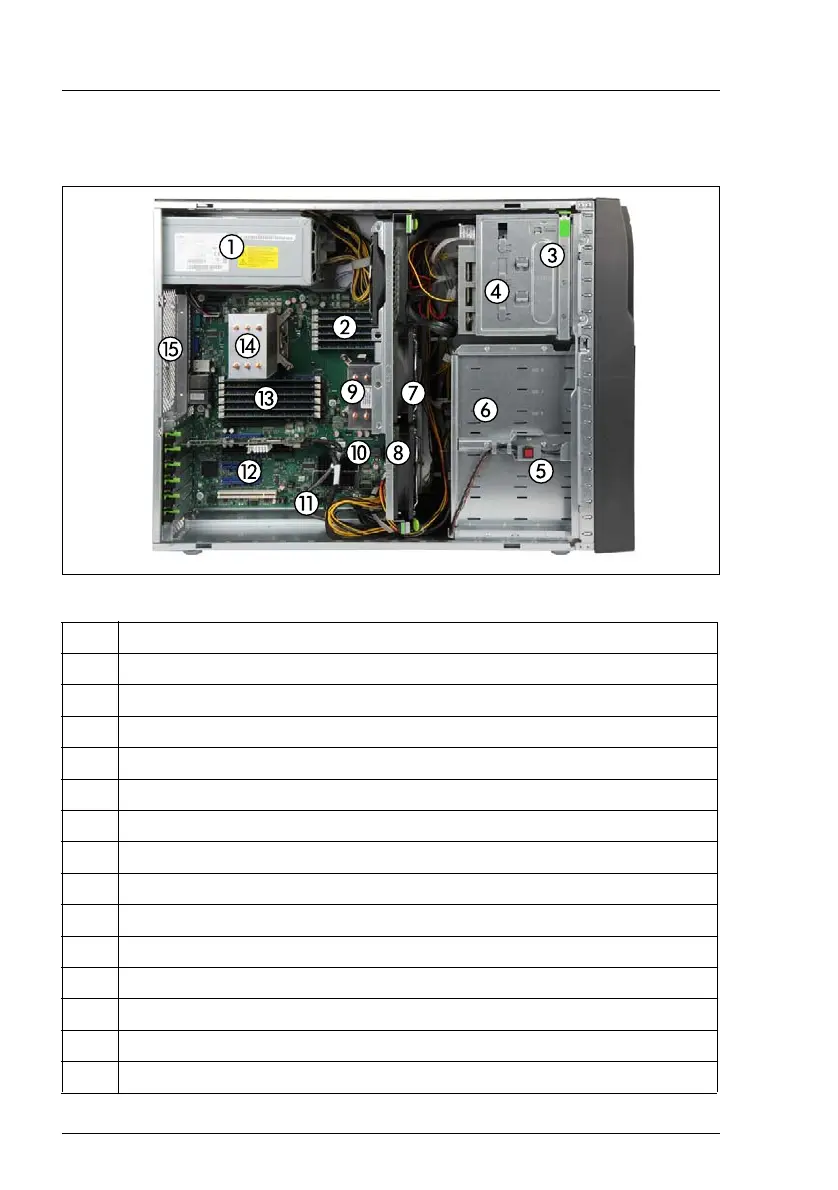
17.1.3 Server interior
Figure 330: Interior (example: 2.5-inch HDD tower model)
1 Power supply unit (photo shows the standard power supply unit)
2 Memory modules (for CPU 1)
3 Front panel module bay
4 Accessible drive bay
5 Intrusion switches
6 HDD / SSD drive bays
7 System fans (fans 1-3)
8 CMOS battery (not visible, located under the system fan 1
9 CPU 1 / CPU heat sink
10 UFM board (if installed)
11 TPM board (if installed)
12 Expansion card slots 1-6
13 Memory modules (for CPU 2)
14 CPU 2 / CPU heat sink
15 Optional system redundant fan (if installed)

 Loading...