362 Upgrade and Maintenance Manual
TX150 S8 / TX200 S7
System board and components
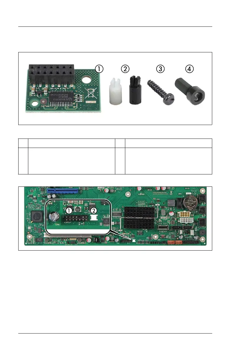
14.4.1.2 Installing the TPM
Figure 275: TPM kit
Figure 276: TPM mounting location
– 1: TPM connector
– 2: Cut-out for TPM spacer
1 TPM (Trusted Platform Module) 3 Special screw for TPM
2 TPM spacer
I The black TPM spacer is
not used in this server.
4 TPM bit insert for TPM special
screw

 Loading...