General Precautions of EFI System Maintenance
F-20
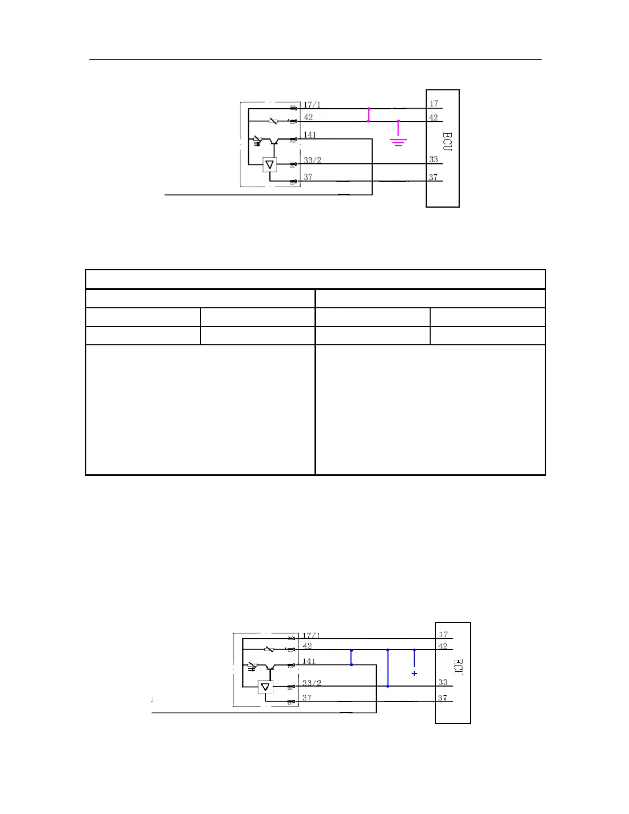
Malfunction Diagnostic Guide:
Required Equipment: (Diagnostic Instrument with EOBD Diagnostic Function, Digital Multimeter, and
Correct Circuit Diagram)
Step I: Use diagnostic instrument to read the malfunction information
Read Result I Read Result II
MIL Lamp On P-CODE Present MIL Lamp Off P-CODE Present
P0112
P0112
Maintenance tips:
The malfunction has been confirmed, and the
following problems may possibly exist
1) The circuit connected to the Pin 45# of ECU and
the circuit for the Pin 17# of ECU in short
circuit
2) The circuit connected to the Pin 42# of ECU and
the ground in short circuit
Maintenance tips:
The malfunction is not ultimately confirmed and it
may possibly be a random malfunction. Inspect the
following items:
1) Measure the electric resistance of the circuit
between the Pin 42# of ECU and the Pin 17# of
ECU.
2) Measure the electric resistance between the Pin
42 of ECU and the ground.
21. P0113 Intake Temperature Sensor Signal Voltage too High
Description about Malfunction Cause:
After engine has been started, ECU performs continuous monitoring over intake temperature, and it will be
determined to be the circuit of intake temperature sensor short to power supply if it is found that the engine
intake temperature exceeds the system set upper limit value.
Schematic Circuit:
Main relay
Main relay