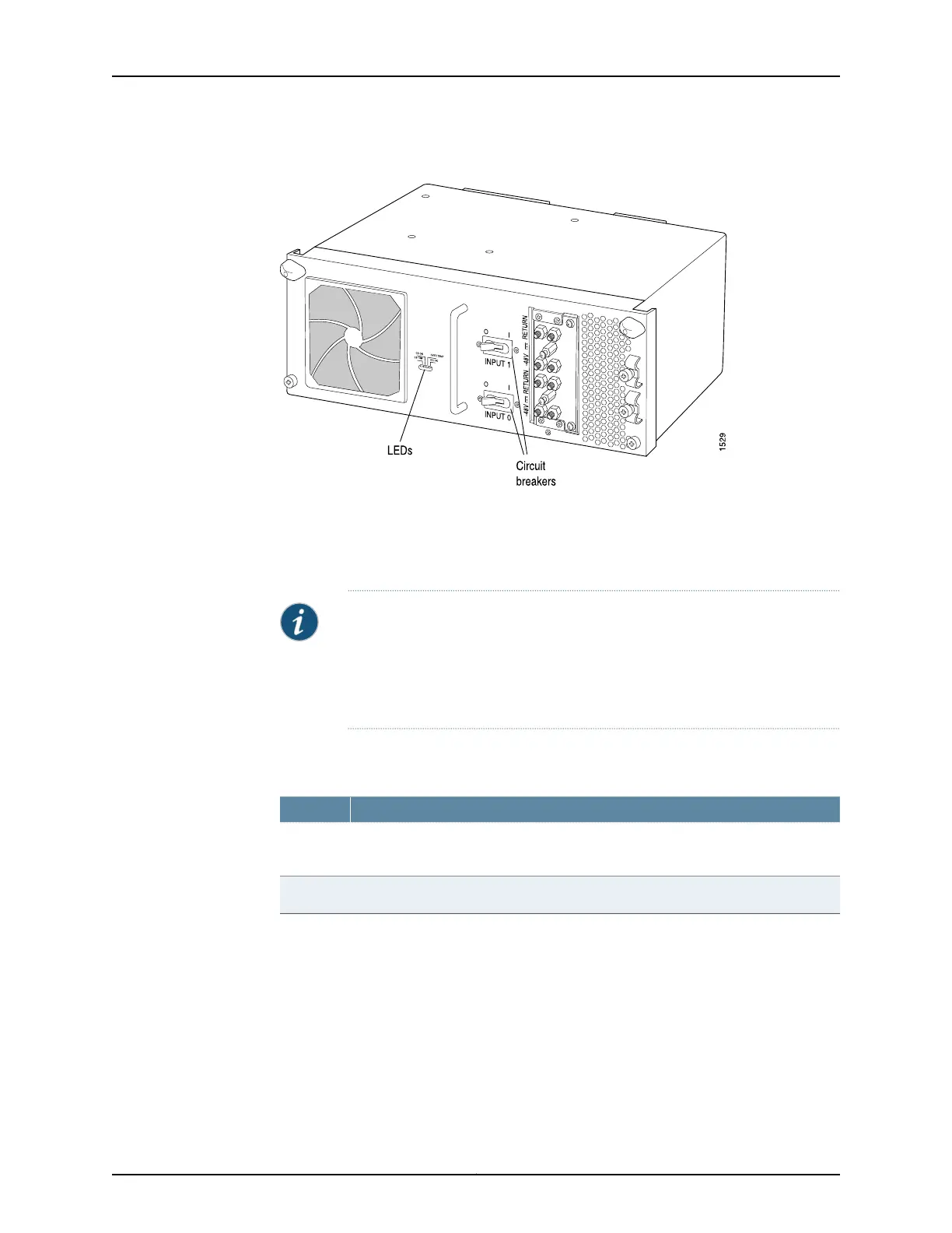
Figure 36: Two-Input 160-A DC Power Supply
Two-Input 160-A DC Power Supply Inputs
Each two-input 160-A DC power supply has two inputs—INPUT 1 and INPUT 0, from top
to bottom—each with its own 80-A (@ –48 VDC) circuit breaker.
NOTE: All inputs on the two-input 160-A DC power supply in slot PEM0 must
be powered by dedicated power feeds derived from feed A, and all inputs on
the two-input 160-A DC power supply in slot PEM1 must be powered by
dedicated power feeds derived from feed B. This configuration provides the
commonly deployed A/B feed redundancy for the system.
Table 52 on page 97 describes which components are powered by each input.
Table 52: Components Powered by Each Input
Provides Power to These ComponentsInput
FPCs in slots FPC0 and FPC1, SIBs, control boards, Routing Engines, CIP, craft interface,
and fan trays
INPUT 0
FPCs in slots FPC2 through FPC7INPUT 1
Two-Input 160-A DC Power Supply Load Sharing and Fault Tolerance
When the router is operating normally and both power supplies in a redundant power
system are switched on, load sharing between them occurs automatically. When one
power supply fails or is turned off, the other power supply immediately assumes the
entire electrical load for the system. A single power supply with both inputs active can
provide full power for as long as the router is operational. Table 53 on page 98 describes
the behavior of the two-input 160-A DC power supply and router if one of the inputs fails.
97Copyright © 2017, Juniper Networks, Inc.
Chapter 7: Power System Components and Descriptions

 Loading...


