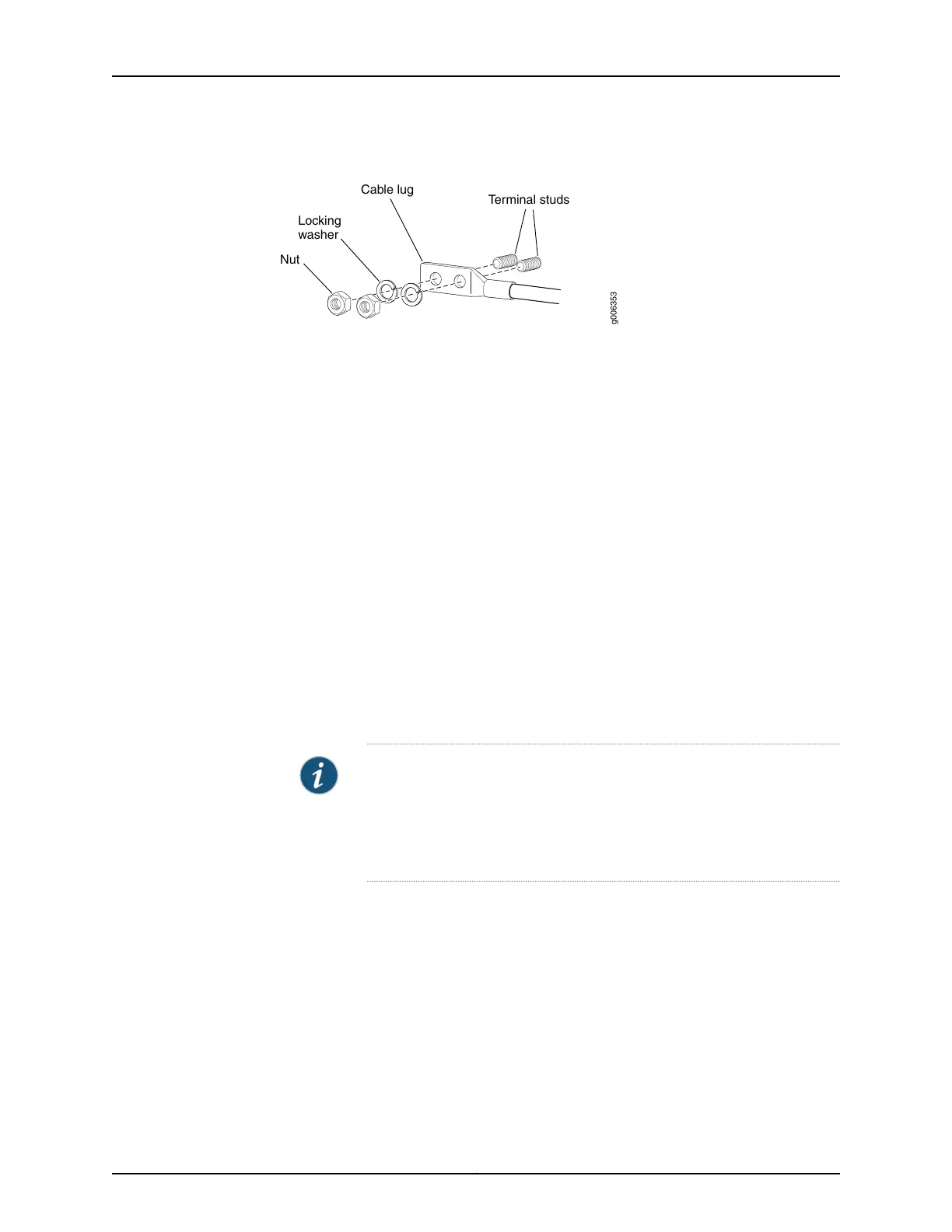
Figure 202: Connecting the DC Power Cable
g006353
Terminal studs
Cable lug
Locking
washer
Nut
4. Tighten the cable restraint captive screw or screws to hold the power cable in place.
5. Replace the clear plastic cover over the terminal studs on the faceplate.
6. Verify that the DC source power cabling is correct, that the power cable is not touching
or blocking access to router components, and that it does not drape where people
could trip on it.
7. Attach the other end of the power cable to the external DC power source.
8. Switch on the customer site circuit breakers.
9. Verify that the INPUT PRESENT LEDs on the power supply faceplate are lit steadily,
indicating that the inputs are receiving voltage.
10. Switch the power switch on the power supply to the ON position (|). The DC OK LED
blinks momentarily, then lights steadily.
NOTE: After a power supply is powered on, it can take up to 60 seconds
forstatusindicators—such as the LEDs on the powersupply, the command
output displays, and messages on the LED display on the craft interface—to
indicate that the power supply is functioning normally. Ignore error
indicators that appear during the first 60 seconds.
11. Verify that the DC OK LED on the power supply faceplate is lit steadily, indicating that
the power supply is correctly installed and is functioning properly.
Related
Documentation
T640 Power System Description on page 95•
• T640 Six-Input DC Power Supply Description on page 104
• T640 Six-Input DC Power Supply LEDs on page 105
• Troubleshooting the T640 Power System on page 476
• T640 DC Power Supply Electrical Specifications on page 126
Copyright © 2017, Juniper Networks, Inc.388
T640 Core Router Hardware Guide

 Loading...


