Related
Documentation
T640 Hardware Component Overview on page 13•
• T640 Router Description on page 3
• T640 Physical Specifications on page 119
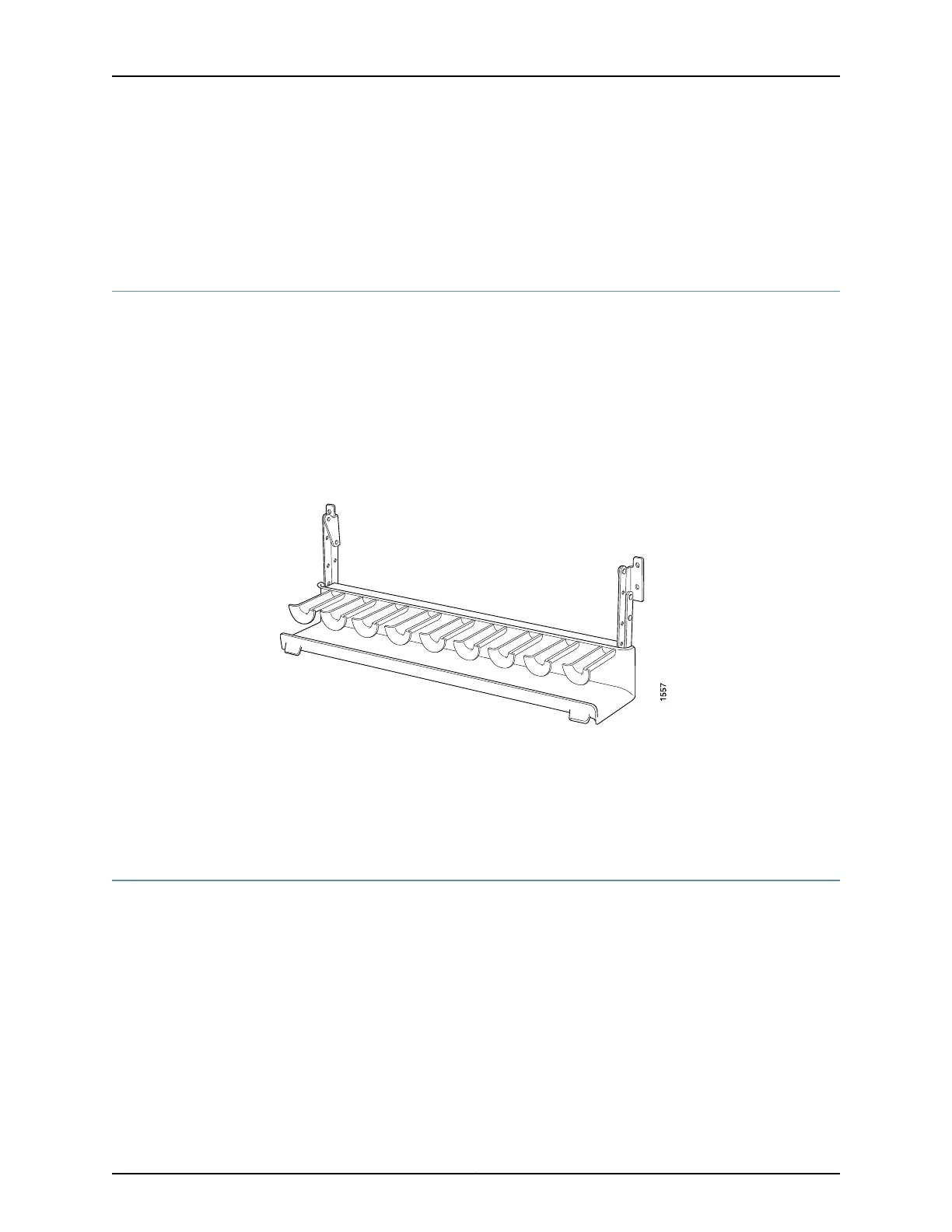
T640 Cable Management System Description
The cable management system (see Figure 7 on page 19) consists of a row of nine
semicircular plastic bobbins mounted on the front of the router below the FPC card cage.
The PIC cables pass between the bobbins and into the tray, keeping the cables organized
and securely in place. The curvature of the bobbins also helps maintain the proper bend
radius for optical PIC cables.
You can pull the cable management system up and outward to lock it into the
maintenance position. This allows you to access the lower fan tray and the front air filter.
Figure 7: Cable Management System
Related
Documentation
T640 Hardware Component Overview on page 13•
• T640 Router Description on page 3
• T640 Chassis Description on page 15
T640 Connector Interface Panel (CIP) Description
•
CIP Components on page 19
•
Management Ports on page 20
•
Alarm Relay Contacts on page 21
CIP Components
The Connector Interface Panel (CIP) consists of Ethernet, console, and auxiliary
connectors for the Routing Engines and alarm relay contacts (see Figure 8 on page 20).
19Copyright © 2017, Juniper Networks, Inc.
Chapter 3: Chassis Components and Descriptions

 Loading...


