10. Tighten the captive screws on each side of the quiet lower front fan tray faceplate to
secure it in the chassis.
11. Unlock the cable management system and lower it to the fully lowered position.
12. Rearrange the PIC cables in the cable management system. For more information
about proper cable arrangement, see “Maintaining T640 PICs and PIC Cables” on
page 454.
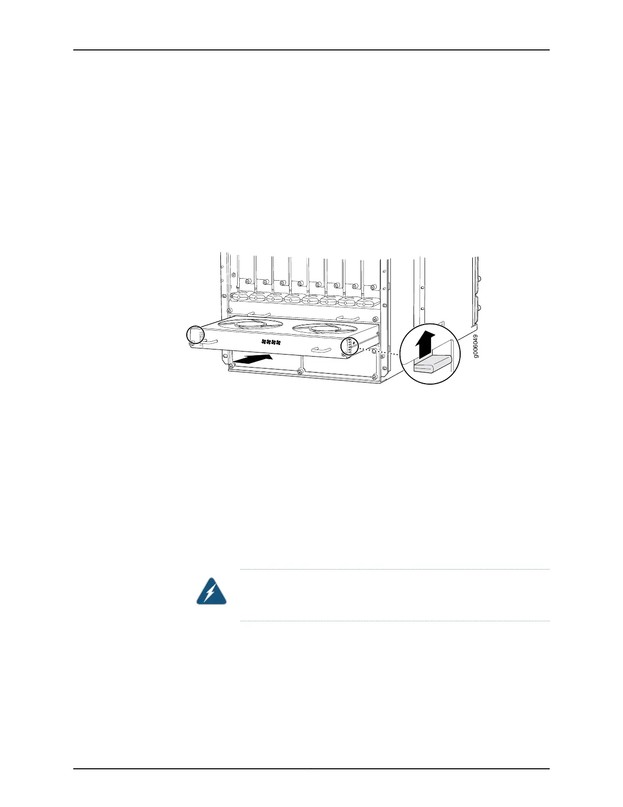
Figure 134: Installing a Quiet Lower Front Fan Tray
g006049
FA N T-F BOT -S
LOWER FANTR AY
Removing the Standard Upper Front Fan Tray
The upper front fan tray is located above the FPC card cage. Each standard front fan tray
weighs about 18.6 lb (8.4 kg). The fan trays are hot-removable.
To remove a standard upper front fan tray (see Figure 135 on page 295):
1. Attach an electrostatic discharge (ESD) grounding strap to your wrist, and connect
the strap to one of the ESD points on the chassis.
2. Loosen the captive screws on the corners of the fan tray faceplate.
3. Grasp the handles and pull the fan tray halfway out of the chassis.
WARNING: To avoid injury, keep tools and your fingers away from the fans
asyou slide the fan tray out of the chassis. The fansmight still be spinning.
4. When the fans stop spinning, place one hand under the fan tray to support it and pull
the fan tray completely out of the chassis.
Copyright © 2017, Juniper Networks, Inc.294
T640 Core Router Hardware Guide

 Loading...


