Home
Juniper
Network Router
T640
Juniper T640 Hardware Guide
5
of 1
of 1 rating
580 pages
Give review
Manual
Specs
To Next Page
To Next Page
To Previous Page
To Previous Page
Loading...
Figure
171:
Remo
ving
a
T
wo-Input
160-A
Pow
er
Suppl
y
Figure
172:
R
ear
of
the
P
ow
er
Suppl
y
Showing
Midpl
ane
Connect
ors
Installing
a
T640
T
wo-Input
DC
Pow
er
Suppl
y
T
o
install
a
power
supply
(see
Figure
173
on
page
355
):
Cop
yright
©
2017
,
Juniper
Network
s,
Inc.
352
T640
Core
Router
Hardware
Guide
385
387
Table of Contents
Table of Contents
3
Default Chapter
29
About the Documentation
29
Documentation and Release Notes
29
Documentation Conventions
29
Supported Platforms
29
Table 1: Notice Icons
30
Table 2: Text and Syntax Conventions
30
Documentation Feedback
31
About the Documentation
31
Opening a Case with JTAC
32
Requesting Technical Support
32
Self-Help Online Tools and Resources
32
Overview
35
Chapter 1 System Overview and Architecture
35
Chassis Components and Descriptions
35
Line Card Components and Description
35
Host Subsystem Components and Descriptions
35
System Overview and Architecture
37
T640 Router Description
37
T640 Component Redundancy
38
Figure 1: Router Architecture
39
T640 Routing Engine Functions
39
T640 System Architecture Description
39
Figure 2: Control Packet Handling for Routing and Forwarding Table Updates
40
Data Flow through the T640 Router
41
T640 Packet Forwarding Engine Architecture
41
Figure 3: Data Flow through the T640 Router
42
Chapter 2 T640 Router Release Notes
45
T640 Router Release Notes
45
Outstanding Issues with the T640 Router
45
Errata with the T640 Router Documentation
46
Chassis Components and Descriptions
47
Chapter 3 Chassis Components and Descriptions
47
T640 Hardware Component Overview
47
Table 3: T640 Hardware Components
47
T640 Chassis Description
49
Figure 4: Front View of T640 Chassis
50
T640 Midplane Description
51
Figure 5: Rear View of T640 Chassis
51
Figure 6: T640 Midplane
52
T640 Cable Management System Description
53
T640 Connector Interface Panel (CIP) Description
53
CIP Components
53
Figure 7: Cable Management System
53
Figure 8: CIP
54
Management Ports
54
Alarm Relay Contacts
55
T640 Connector Interface Panel (CIP) Leds
56
T640 Craft Interface Description
56
Table 4: CIP Leds
56
T640 Craft Interface Alarm Leds and ACO/LT Button
57
Figure 9: Front Panel of the T640 Craft Interface
57
T640 Craft Interface FPC Leds and Online/Offline Buttons
58
T640 Craft Interface Host Subsystem Leds
58
Table 5: Alarm Leds and Alarm Cutoff/Lamp Test Button
58
Table 6: FPC Leds
58
T640 Craft Interface LCD and Navigation Buttons
59
Figure 10: T640 LCD in Idle Mode
59
Table 7: T640 Host Subsystem Leds
59
T640 Craft Interface SIB Leds
60
Figure 11: T640 LCD in Alarm Mode
60
Table 8: SIB Leds on the Craft Interface
60
T640 SONET Clock Generators (Scgs) Description
61
Figure 12: SCG with DB-9 Ports
61
Table 9: Supported Power Supplies
61
T640 SONET Clock Generators (Scgs) Leds
62
Figure 13: SCG with RJ-48 Ports
62
Figure 14: SCG with RJ-48 Ports
63
Table 10: SCG Leds
63
Chapter 4 Cooling System Components and Descriptions
65
T640 Cooling System Description
65
Airflow
65
Fan Trays
66
Figure 15: Airflow through the Chassis
66
Air Filters
67
Power Supply Cooling System
67
Cooling System Components and Descriptions
67
Figure 16: Quiet Upper Front Fan Tray
67
Figure 17: Quiet Lower Front Fan Tray
67
Chapter 5 Host Subsystem Components and Descriptions
69
T640 Host Subsystem Description
69
T640 Routing Engine Description
70
T640 RE-600 Description
71
Host Subsystem Components and Descriptions
71
Table 11: T640 Supported Routing Engines
71
T640 RE-600 Leds
73
T640 RE-1600 Description
73
Figure 18: Routing Engine 600
73
Table 12: Routing Engine 600 Leds
73
Figure 19: Routing Engine 1600 (RE-1600)
74
T640 Re-1600 Leds
75
Table 13: Routing Engine 1600 Leds
75
T640 RE-C1800 Description
76
RE-C1800 Components
76
RE-C1800 Boot Order
76
Figure 20: Routing Engine C1800 (RE-C1800)
76
Documentation
77
T640 Host Subsystem Description
77
T640 Routing Engine Description
77
T640 RE-1600 Leds
77
Label Color State
77
Figure 21: RE-C1800 Leds
77
Related T640 Hardware Component Overview
77
T640 RE-C1800 Leds
77
Table 14: Routing Engine C1800 Leds
77
T640 RE-2000 Description
78
Green on Steadily
78
Figure 22: Routing Engine 2000 (RE-2000)
79
T640 RE-2000 Leds
79
Table 15: Routing Engine 2000 Leds
79
Documentation
80
T640 Routing Engine Description
80
T640 RE-1600 Description
80
Troubleshooting the T640 Host Subsystem
80
Table 17: End-Of-Life Routing Engine Specifications
82
Routing Engine Specifications
80
Table 16: Routing Engine Specifications
80
Routing-Related Activity
80
Supported Routing Engines by Router
83
M7I Routing Engines
84
M10I Routing Engines
84
Table 18: M7I Routing Engines
84
Table 19: M10I Routing Engines
84
M40E Routing Engines
85
M120 Routing Engines
85
M320 Routing Engines
85
Table 20: M40E Routing Engines
85
Table 21: M120 Routing Engines
85
MX5, MX10, MX40, and MX80 Routing Engine
86
MX104 Routing Engines
86
Table 22: M320 Routing Engines
86
Table 23: MX5, MX10, MX40, and MX80 Routing Engine
86
MX240 Routing Engines
87
MX480 Routing Engines
87
Table 24: MX104 Routing Engines
87
Table 25: MX240 Supported Routing Engines
87
MX960 Routing Engines
88
Table 26: MX480 Supported Routing Engines
88
Table 27: MX960 Supported Routing Engines
88
MX2008 Routing Engines
89
MX2010 Routing Engines
89
Table 28: MX2008 Supported Routing Engines
89
MX2020 Supported Routing Engines
90
PTX3000 Routing Engines
90
Table 29: MX2010 Supported Routing Engines
90
Table 30: MX2020 Supported Routing Engines
90
PTX5000 Routing Engines
91
T320 Routing Engines
91
Table 31: PTX3000 Routing Engines
91
Table 32: PTX5000 Routing Engines
91
Table 33: T320 Routing Engines
91
T640 Routing Engines
92
T1600 Routing Engines
92
Table 34: T640 Routing Engines
92
T4000 Routing Engines
93
Table 35: T1600 Routing Engines
93
TX Matrix Routing Engines
94
TX Matrix Plus Routing Engines
94
Table 36: T4000 Routing Engines
94
Table 37: TX Matrix Routing Engines
94
TX Matrix Plus (with 3D Sibs) Routing Engines
95
Figure 23: LCC-CB
95
T640 LCC-CB Description
95
Table 38: TX Matrix Plus Routing Engines
95
Table 39: Routing Engines on TX Matrix Plus with 3D Sibs
95
Figure 24: LCC-CB Leds
96
T640 LCC-CB Leds
96
Table 40: LCC-CB Leds
96
T640 Standard Control Boards Description
97
Default Chapter
97
Figure 25: T640 Standard Control Board
97
T640 Standard Control Boards Leds
98
T640 T Series Control Boards (T-Cbs) Description
98
Table 41: Standard Control Board Leds
98
Figure 26: T-CB
99
Related T640 Hardware Component Overview
99
T640 Control Boards Description
99
T640 Host Subsystem Description
99
T640 T Series Control Boards (T-Cbs) Leds
100
Table 42: T-CB Leds
100
T640 Host Subsystem Description
100
Troubleshooting the T640 Control Board
100
Troubleshooting the T640 Host Subsystem
100
Chapter 6 Line Card Components and Description
101
T640 FPC Description
101
Figure 27: FPC Installed in a T640 Chassis
102
FPC Terminology
102
Figure 28: FPC Edges
103
Identifying T640 Fpcs
103
Table 43: Identifying the Fpcs Supported by the T640 Router
103
Figure 29: Enhanced Scaling FPC1 Supported by the T640 Router
105
Figure 30: Standard FPC2 and FPC3 Supported by the T640 Router
106
Figure 31: Enhanced II FPC1, FPC2, and FPC3 Supported by the T640 Router
107
Figure 32: Enhanced Scaling FPC2 Supported by the T640 Router
108
Figure 33: Enhanced Scaling FPC3 Supported by the T640 Router
109
Figure 34: Enhanced Scaling FPC4 Supported by the T640 Router
110
T640 Fpcs Supported
111
Figure 35: T640 Enhanced Scaling FPC4-1P Supported by the T640 Router
111
Table 44: Fpcs Supported by the T640 Router
112
T640 PIC Description
113
T640 Pics Supported
114
Table 45: Pics Supported in the T640 Router
114
T640 End-Of-Life Pics Supported
121
Table 46: End-Of-Life Pics Supported in the T640 Router
121
T640 PIC/FPC Compatibility
123
PIC/FPC Compatibility (Type 1 Fpcs and Type 1 Pics)
123
PIC/FPC Compatibility (Type 2 Fpcs and Type 2 Pics)
124
Table 47: T640 PIC/FPC Compatibility Type 1
124
PIC/FPC Compatibility (Type 3 Fpcs and Type 3 Pics)
126
Table 48: T640 PIC/FPC Compatibility Type 2
126
PIC/FPC Compatibility (Type 4 Fpcs and Type 4 Pics)
127
Table 49: T640 PIC/FPC Compatibility Type 3
127
Table 50: T640 PIC/FPC Compatibility Type 4
128
Power System Components and Descriptions
129
Chapter 7 Power System Components and Descriptions
129
T640 Power System Description
129
T640 Two-Input 160-A DC Power Supply Description
130
Table 51: Supported Power Supplies
130
Two-Input 160-A DC Power Supply
130
Figure 36: Two-Input 160-A DC Power Supply
131
Table 52: Components Powered by each Input
131
Two-Input 160-A DC Power Supply Inputs
131
Two-Input 160-A DC Power Supply Load Sharing and Fault Tolerance
131
T640 Two-Input 160-A DC Power Supply Leds
132
Table 53: Fault Tolerance
132
Table 54: Two-Input 160-A DC Power Supply Leds
132
T640 Power System Description
132
T640 Three-Input 240-A DC Power Supply Description
133
Figure 37: Three-Input 240-A DC Power Supply
133
Three-Input 240-A DC Power Supply
133
Three-Input 240-A DC Power Supply Inputs
133
Three-Input 240-A DC Power Supply Load Sharing and Fault Tolerance
134
T640 Three-Input 240-A DC Power Supply Leds
134
Table 55: Components Powered by each Three-Input 240-A DC Power Supply
134
Table 56: Fault Tolerance
134
Figure 38: Three-Input 240-A DC Power Supply Leds
135
Table 57: Three-Input 240-A DC Power Supply Leds
135
T640 Four-Input 240-A DC Power Supply Description
136
Figure 39: Four-Input 240-A DC Power Supply
136
Four-Input 240-A DC Power Supply
136
Four-Input 240-A DC Power Supply Inputs
136
Table 58: Components Powered by each Four-Input 240-A DC Power Supply
136
Four-Input 240-A DC Power Supply Load Sharing and Fault Tolerance
137
T640 Four-Input 240-A DC Power Supply Leds
137
Figure 40: Four-Input 240-A DC Power Supply Leds
137
Table 59: Four-Input 240-A DC Power Supply Leds
137
T640 Six-Input DC Power Supply Description
138
Power Supply Components
138
Inputs
139
Redundancy
139
T640 Six-Input DC Power Supply Leds
139
Figure 41: Six-Input DC Power Supply
139
Table 60: Components Powered by each Six-Input DC Power Supply Input
139
T640 Three-Phase Delta and Wye AC Power Supply Description
140
Table 61: Six-Input DC Power Supply Leds
140
Three-Phase Delta AC Power Supply
140
Figure 42: Three-Phase Delta AC Power Supply
141
Figure 43: Three-Phase Delta AC Power Supply Connections
141
Figure 44: Three-Phase Delta AC Power Cord
142
Figure 45: Three-Phase Wye AC Power Supply
142
Three-Phase Wye AC Power Supply
142
AC Power Supply Load Sharing and Fault Tolerance
143
T640 Three-Phase Delta and Wye AC Power Supply Leds
143
Figure 46: Three-Phase Wye AC Power Supply Connections
143
Figure 47: Wye Three-Phase AC Power Cord
143
Figure 48: Delta AC Power Supply Leds
144
Table 62: Delta AC Power Supply Leds
144
Chapter 8 Switch Fabric Components and Descriptions
145
T640 Switch Interface Boards (Sibs) Description
145
Table 63: Links to the Sibs from the Fpcs
145
Figure 49: Standard SIB or Standard SIB Version B
146
Figure 50: T640-SIB
146
Site Planning, Preparation, and Specifications
149
Preparation Overview
151
T640 Site Preparation Checklist
151
Table 64: Site Preparation Checklist
151
Table 65: T640 Physical Specifications
151
Chapter 9 Preparation Overview
151
T640 Chassis Grounding Cable and Lug Specifications
152
Figure 51: T640 DC Power and Grounding Cable Lug
153
T640 Physical Specifications
153
T640 Rack Requirements
154
Figure 52: Typical Open-Frame Rack
155
Figure 53: T640 Chassis Dimensions and Clearance Requirements
156
T640 Clearance Requirements for Airflow and Hardware Maintenance
156
T640 Environmental Specifications
156
Table 66: Router Environmental Specifications
157
Chapter 10 DC Power Requirements and Specifications
159
T640 DC Power System Electrical Specifications
159
Table 67: T640 Power System Electrical Specifications
159
T640 DC Power Supply Electrical Specifications
160
Table 68: T640 Two-Input 160-A DC Power Supply Electrical Specifications
160
Table 69: T640 Three-Input 240-A DC Power Supply Electrical
160
Table 70: Four-Input 240-A DC Power Supply Electrical Specifications
161
Table 71: Six-Input DC Power Supply Electrical Specifications
161
T640 DC Power System Requirements
162
Table 72: T640 Component DC Power Requirements
162
T640 DC Power Distribution
164
Figure 54: Typical DC Source Cabling from PEM0 to Feed a
165
Figure 55: Typical DC Source Cabling from PEM1 to Feed B
165
T640 DC Power Cable and Lug Specifications
166
Figure 56: T640 DC Power Cable Lug
166
Table 73: Number of Cables Required
166
Table 74: T640 Power Cable Specifications
166
Chapter 11 AC Power Requirements and Specifications
169
T640 AC Power System Specifications
169
Table 75: T640 AC Power System Electrical Specifications
169
T640 Three-Phase Delta AC Power Supply Specifications
170
T640 Three-Phase Wye AC Power Supply Specifications
170
Table 76: Three-Phase Delta AC Power Supply Electrical Specifications
170
Table 77: Three-Phase Wye AC Power Supply Electrical Specifications
170
T640 AC Power Requirements
171
Table 78: T640 Base AC Power Requirements
171
Table 79: Typical AC Power Requirements for T640 Components
171
T640 AC Power Cord Specifications
173
Figure 57: Three-Phase Delta AC Power Cord
173
Table 80: Three-Phase Delta and Wye AC Power Cord Specifications
173
Figure 58: Three-Phase Wye AC Power Cord
174
Chapter 12 Network Cable and Transceiver Planning
175
Understanding Fiber-Optic Cable Signal Loss, Attenuation, and Dispersion
175
Attenuation and Dispersion in Fiber-Optic Cable
175
Signal Loss in Multimode and Single-Mode Fiber-Optic Cable
175
Calculating Power Budget and Power Margin for Fiber-Optic Cables
176
Calculating Power Budget for Fiber-Optic Cable
176
Calculating Power Margin for Fiber-Optic Cable
177
Table 81: Estimated Values for Factors Causing Link Loss
177
Chapter 13 Management Cable Specifications and Pinouts
179
T640 Routing Engine Interface Cable and Wire Specifications
179
Table 82: Cable and Wire Specifications for Routing Engine Management and Alarm Interfaces
179
T640 DB-9 Connector Pinouts for the Routing Engine AUXILIARY and CONSOLE Ports
180
T640 RJ-45 Connector Pinouts for the Routing Engine ETHERNET Port
180
Table 83: DB-9 Connector Pinouts
180
Table 84: RJ-45 Connector Pinouts
180
Initial Installation and Configuration
183
Installation Overview
185
T640 Router Installation Summary
185
Chapter 14 Installation Overview
185
Chapter 15 Unpacking the T640
187
Tools and Parts Required to Unpack the T640 Router
187
Unpacking the T640 Router
187
Verifying the T640 Router Parts Received
189
Figure 59: Contents of the Shipping Crate
189
Table 85: Router Parts List
189
Table 86: Accessory Box Parts List
191
Chapter 16 Installing the Rack Mounting Hardware
193
Installing the T640 Mounting Hardware for a Four-Post Rack or Cabinet
193
Table 87: T640 Four-Post or Cabinet Rack Mounting Hole Locations
193
Figure 60: Positioning the Spacer Bar on the Rack
195
Installing the T640 Mounting Hardware for an Open-Frame Rack
196
Figure 61: Installing the Mounting Hardware for a Four-Post Rack or Cabinet
196
Figure 62: Installing the Mounting Hardware for an Open-Frame Rack
198
Table 88: T640 Open-Frame Rack Mounting Hole Locations
198
Chapter 17 Installing the T640 Router into a Rack
201
Overview of Installing the T640 Router in a Rack
201
Chapter 18 Installing the T640 Router with a Mechanical Lift
203
Overview of Installing a T640 Router Using a Mechanical Lift
203
Tools Required to Install the T640 Router Using a Mechanical Lift
203
Installing the T640 Router Using a Mechanical Lift
204
Removing the T640 Power Supplies
204
Removing the T640 Router Installation Handle and Reinstalling the Power
204
Attaching the T640 Router Installation Handle
205
Figure 63: Removing a Power Supply before Installing the Router
205
Figure 64: Removing a Power Supply before Installing the Installation
206
Figure 65: Attaching the Installation Handle
207
Mounting the T640 Chassis Using a Mechanical Lift
207
Figure 66: Loading the Router Onto the Lift
209
Figure 67: Installing the Router in the Rack
210
Supplies
210
Figure 68: Reinstalling a Power Supply
211
Chapter 19 Installing the T640 Router Without a Mechanical Lift
213
Overview of Installing the T640 Router Without a Mechanical Lift
213
Lift
214
Removing Components from the T640 Chassis
214
Removing the T640 Power Supplies
215
Figure 69: Removing a Power Supply before Installing the Router
216
Removing the T640 Sibs
216
Figure 70: Removing a SIB
217
Removing the T640 Control Boards
217
Figure 71: Removing a T-CB
218
Figure 72: Removing an LCC-CB
218
Removing the T640 Scgs
218
Figure 73: Removing an SCG
219
Removing the T640 Standard or Quiet Rear Fan Tray
219
Figure 74: Removing the Rear Fan Tray
220
Removing the T640 Cable Management System
220
Removing the T640 Standard or Quiet Front Fan Trays
221
Figure 75: Removing the Standard Upper Front Fan Tray
222
Figure 76: Removing the Quiet Upper Front Fan Tray
222
Removing the T640 Fpcs
222
Attaching the T640 Router Installation Handle
224
Figure 77: Removing a T640 FPC
224
Installing the T640 Chassis in the Rack Manually
226
Figure 78: Removing a Power Supply before Installing the Installation
226
Figure 79: Attaching the Installation Handle
226
Figure 80: Attaching the Installation Handle
227
Reinstalling Components in the T640 Chassis
229
Figure 81: Installing the Router in the Rack
229
Reinstalling the T640 Standard or Quiet Rear Fan Tray
230
Figure 82: Reinstalling the Rear Fan Tray
231
Reinstalling the T640 Scgs
231
Figure 83: Reinstalling an SCG
232
Figure 84: Reinstalling a T-CB
232
Reinstalling the T640 Control Boards
232
Figure 85: Reinstalling an LCC-CB
233
Reinstalling the T640 Sibs
233
Figure 86: Reinstalling a SIB
234
Reinstalling the T640 Power Supplies
234
Figure 87: Reinstalling a Power Supply
235
Reinstalling the T640 Fpcs
235
Figure 88: Reinstalling an FPC
236
Reinstalling T640 Standard or Quiet Front Fan Trays
237
Figure 89: Reinstalling the Quiet Upper Front Fan Tray
238
Figure 90: Reinstalling the Quiet Lower Front Fan Tray
238
Figure 91: Reinstalling the Standard Upper Front Fan Tray
238
Reinstalling the T640 Cable Management System
239
Chapter 20 Connecting the T640 to Ground
241
Tools and Parts Required to Ground the T640 Router
241
Figure 92: Grounding Lug
241
Connecting the T640 Grounding Cable
242
Chapter 21 Connecting the T640 to External Devices
243
Overview of Connecting the T640 Router to External Devices
243
Tools and Parts Required to Connect the T640 Router to External Devices
244
Connecting the T640 Router to a Management Console or Auxiliary Device
244
Figure 93: Console and Auxiliary Serial Port Connector
245
Figure 94: Console and Auxiliary Ports on the CIP
245
Connecting the T640 Router to a Network for Out-Of-Band Management
246
Figure 95: Routing Engine Ethernet Cable Connector
246
Figure 96: ETHERNET Port on the CIP
247
Connecting the T640 Router to an External Alarm-Reporting Device
248
Connecting the T640 Router to an External Clocking Device
249
Connecting PIC Cables to the T640 Router
250
Figure 97: Attaching a Cable to a PIC
251
Chapter 22 Providing Power to the T640
253
Tools and Parts Required to Provide Power to the T640 Router
253
Supplies
254
Connecting DC Power to a T640 Router with Three-Input 240-A DC Power Supplies (2-INPUT Mode)
256
Figure 98: Connecting DC Power to a Two-Input 160-A DC Power Supply
256
Figure 99: Connecting DC Power to a Three-Input 240-A DC Power Supply in
258
Figure 100: Connecting Power to the Four-Input 240-A DC Power Supply
260
Supplies
261
Connecting DC Power to the T640 Router (Six 60-A Inputs to Six-Input DC Power Supplies)
261
Connecting DC Power to the T640 Router
261
Figure 101: Connecting DC Power Cables
263
Figure 102: Connecting Negative (-) DC Power Cables to INPUT 0, INPUT
263
Figure 103: Connecting Negative (-) DC Power Cables to INPUT 2 and
264
Figure 104: Connecting Positive (+) DC Power Cables to RTN 2, RTN 5, RTN
265
Power Supplies)
265
Figure 105: Connecting DC Power Cables
267
Figure 106: Connecting Negative (-) DC Power Cables to INPUT 0, INPUT
268
Figure 107: Connecting Negative (-) DC Power Cable to INPUT 2
268
Figure 108: Connecting Positive (+) DC Power Cable to RTN 2, RTN 0, RTN
269
Connecting DC Power to the T640 Router (Four 60-A Inputs to Six-Input DC Power Supplies)
270
Figure 109: Connecting DC Power Cables
272
Figure 110: Connecting Negative (-) DC Power Cables to INPUT 0, INPUT
272
Powering on a DC-Powered T640 Router
273
Figure 111: Connecting Positive (+) DC Power Cables to RTN 0, RTN 1, RTN 3, and
273
Supplies
273
Figure 112: Connecting Power to a Three-Phase Delta AC Power Supply
277
Supplies
278
Figure 113: Connecting Power to the Three-Phase Wye AC Power Supply
279
Powering on an AC-Powered T640 Router
280
Figure 114: Fastening the AC Power Cord to the Power Supply
280
Powering off the T640 Router
282
Chapter 23 Configuring the Junos os Software
285
Preparing to Configure the T640 Router
285
Initially Configuring the T640 Router
285
Configuring User Accounts and Passwords
286
Entering Configuration Mode
286
Configuring System Attributes
287
Committing the Configuration
288
Configuring DC Power on a T640 Router
289
Configuring DC Power on a T640 Router (Five 60-A Cables on a Six-Input DC Power Supply)
289
Configuring DC Power on a T640
290
Power Supply)
290
Chapter 24 Installing and Replacing Components
293
Overview of Installing and Replacing Components
295
T640 Field-Replaceable Units
295
Table 89: Field-Replaceable Units
296
Table 90: Tools and Parts Required for Component Replacement
296
Tools and Parts Required to Replace the T640 Hardware Components
296
Chapter 25 Replacing Chassis Components
299
Replacing a T640 Craft Interface
299
Removing a T640 Craft Interface
299
Figure 115: Removing a Craft Interface
300
Installing a T640 Craft Interface
300
Replacing the T640 CIP
301
Figure 116: Installing a Replacement Craft Interface
301
Removing a T640 CIP
301
Figure 117: Removing a CIP
302
Installing a T640 CIP
302
Replacing the T640 Alarm Relay Wires
304
Figure 118: Installing a CIP
304
Figure 119: Routing Engine Alarm Relay Wires
306
Replacing the T640 Console or Auxiliary Cable
307
Figure 120: Routing Engine Console
308
Replacing the T640 Management Ethernet Cable
309
Figure 121: Ethernet Cable Connectors
310
Replacing a T640 SCG
311
Removing a T640 SCG
311
Figure 122: Removing an SCG
312
Installing a T640 SCG
312
Figure 123: Installing an SCG
313
Chapter 26 Replacing Cooling System Components
315
Replacing a T640 Air Filter
315
Removing a Front T640 Air Filter
315
Figure 124: Removing the Front Air Filter
316
Figure 125: Replacing the Front Filter Element
316
Figure 126: Installing the Front Air Filter
317
Installing a Front T640 Air Filter
317
Removing a Rear T640 Air Filter
317
Figure 127: Removing the Rear Air Filter
318
Figure 128: Removing the Rear Air Filter Element
319
Installing a Rear T640 Air Filter
319
Replacing the T640 Standard Lower Front Fan Tray
320
Figure 129: Installing the Rear Air Filter
320
Installing the T640 Standard Lower Front Fan Tray
321
Removing the T640 Standard Lower Front Fan Tray
321
Replacing the T640 Standard Upper Front Fan Tray
322
Removing the T640 Standard Upper Front Fan Tray
322
Figure 130: Removing a Standard Upper Front Fan Tray
323
Figure 131: Installing an Upper Front Fan Tray
323
Installing the T640 Standard Upper Front Fan Tray
323
Replacing the T640 Standard Rear Fan Tray
324
Removing the T640 Standard Rear Fan Tray
324
Figure 132: Removing the Standard Rear Fan Tray
325
Installing the T640 Standard Rear Fan Tray
325
Upgrading to the T640 Quiet Fan Trays
326
Figure 133: Installing a Rear Fan Tray
326
Upgrading the Standard Lower Front Fan Tray to a Quiet Lower Front Fan Tray
327
Figure 134: Installing a Quiet Lower Front Fan Tray
328
Removing the Standard Upper Front Fan Tray
328
Figure 135: Removing a Standard Upper Front Fan Tray
329
Figure 136: Removing the Craft Interface
329
Removing the Craft Interface
329
Figure 137: Installing the Air Deflector
330
Installing the Air Deflector and Craft Interface
330
Installing the Quiet Upper Front Fan Tray
330
Figure 138: Installing the Quiet Upper Front Fan Tray
331
Upgrading the Standard Rear Fan Tray to a Quiet Rear Fan Tray
331
Figure 139: Removing the Standard Rear Fan Tray
332
Replacing the T640 Quiet Lower Front Fan Tray
333
Figure 140: Installing the Quiet Rear Fan Tray
333
Removing the T640 Quiet Lower Front Fan Tray
334
Figure 141: Removing the Quiet Lower Front Fan Tray
335
Installing the T640 Quiet Lower Front Fan Tray
335
Replacing the T640 Quiet Upper Front Fan Tray
336
Figure 142: Installing the Quiet Lower Front Fan Tray
336
Removing the T640 Quiet Upper Front Fan Tray
336
Figure 143: Removing the Quiet Upper Front Fan Tray
337
Installing the T640 Quiet Upper Front Fan Tray
337
Replacing the T640 Quiet Rear Fan Tray
338
Figure 144: Installing the Quiet Upper Front Fan Tray
338
Removing the T640 Quiet Rear Fan Tray
338
Figure 145: Removing the Quiet Rear Fan Tray
339
Installing the T640 Quiet Rear Fan Tray
339
Figure 146: Installing the Quiet Rear Fan Tray
340
Chapter 27 Replacing Host Subsystem Components
341
Replacing the T640 Host Subsystem Components
341
Table 91: Effect of Taking the Host Subsystem Offline
341
Taking the T640 Host Subsystem Offline
341
Replacing a T640 LCC-CB
344
Removing a T640 LCC-CB
344
Figure 147: Removing an LCC-CB
345
Installing a T640 LCC-CB
346
Replacing a T640 Standard Control Board or T-CB
347
Figure 148: Installing an LCC-CB
347
Removing a T640 Standard Control Board or T-CB
348
Figure 149: Removing a Standard Control Board
349
Figure 150: Removing a T-CB
349
Installing a T640 Standard Control Board or T-CB
349
Figure 151: Installing a Standard Control Board
350
Figure 152: Installing a T-CB
350
Replacing a T640 Routing Engine
351
Removing a T640 Routing Engine
351
Figure 153: Removing the Routing Engine Cover
352
Figure 154: Removing a Routing Engine
352
Installing a T640 Routing Engine
352
Replacing a Compactflash Card in a T640 RE-C1800 Routing Engine
354
Engine
354
Figure 155: Installing a Routing Engine
354
Figure 156: Reinstalling the Routing Engine Cover
354
Preparing to Replace a Compactflash Card in a T640 RE-C180 Routing
354
Removing a Compactflash Card in a T640 RE-C1800 Routing Engine
355
Figure 157: Removing a Compactflash Card
356
Installing a Compactflash Card in a T640 RE-C1800 Routing Engine
356
Figure 158: Installing a Compactflash Card
357
Routing Engine
357
Replacing a DIMM Module in a T640 Routing Engine
358
Installing a T640 DIMM Module
358
Removing a T640 DIMM Module
358
Replacing a PC Card in a T640 Routing Engine
359
Figure 159: Installing the DIMM Module
359
Removing a T640 PC Card
359
Figure 160: Removing a PC Card
360
Installing a T640 PC Card
360
Replacing a Solid-State Disk in a T640 RE-C1800 Routing Engine
361
Engine
361
Figure 161: Installing a PC Card
361
Removing a Solid-State Disk in a T640 RE-C1800 Routing Engine
362
Figure 162: Removing an SSD
363
Installing a Solid-State Disk in a T640 RE-C1800 Routing Engine
363
Engine
364
Figure 163: Installing an SSD
364
Chapter 28 Replacing Line Card Components
367
Replacing a T640 FPC
367
Removing a T640 FPC
367
Figure 164: Removing a T640 FPC
370
Installing a T640 FPC
370
Figure 165: Installing an FPC
372
Replacing a T640 PIC
374
Figure 166: Installing a T640 FPC
374
Removing a T640 PIC
375
Figure 167: Removing a PIC
377
Installing a T640 PIC
377
Figure 168: Installing a PIC
379
Replacing T640 PIC Cables
380
Removing a T640 PIC Cable
380
Installing a T640 PIC Cable
381
Figure 169: Connecting Fiber-Optic Cable to a PIC
382
Chapter 29 Replacing Power System Components
383
Replacing a T640 Two-Input 160-A DC Power Supply
383
Removing a T640 Two-Input 160-A DC Power Supply
383
Figure 170: Disconnecting Power Cables from a Two-Input 160-A DC Power
384
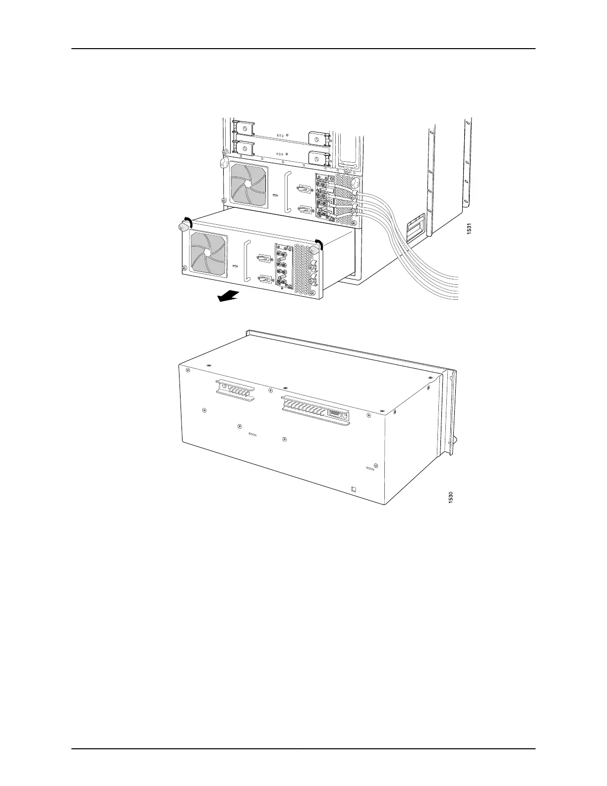
Figure 171: Removing a Two-Input 160-A Power Supply
386
Figure 172: Rear of the Power Supply Showing Midplane Connectors
386
Installing a T640 Two-Input DC Power Supply
386
Figure 173: Installing a Replacement Two-Input 160-A DC Power Supply
389
Replacing a T640 Three-Input 240-A DC Power Supply
390
Figure 174: Connecting Power Cables to a Two-Input 160-A DC Power
390
Removing a T640 Three-Input 240-A DC Power Supply
391
Figure 175: Disconnecting Power Cables from the DC Power Supply
392
Figure 176: Rear of the Power Supply Showing Midplane Connectors
393
Figure 177: Removing a Three-Input 240-A DC Power Supply
393
Figure 178: Three-Input 240-A DC Power Supply
394
Setting the Input Mode Switch on a Three-Input 240-A DC Power Supply for a T640 Router
394
Figure 179: Installing a Three-Input 240-A DC Power Supply
395
Installing a T640 Three-Input 240-A DC Power Supply
395
Installing the T640 Optional Cable Restraint on a Three-Input 240-ADC Power Supply
396
Removing the T640 Standard Cable Restraint from a Three-Input 240-ADC Power Supply
396
Supply
396
Figure 181: Optional Cable Restraint on a Three-Input 240-A DC Power
397
Router
397
Supply
397
Figure 182: Connecting Power Cables to the Power Supply
399
Replacing a T640 Four-Input 240-A DC Power Supply
400
Removing a T640 Four-Input 240-A DC Power Supply
400
Figure 183: Four-Input 240-A DC Power Supply
401
Figure 184: Disconnecting Power Cables from the Four-Input 240-A DC Power
402
Figure 185: Removing a Four-Input 240-A DC Power Supply
403
Figure 186: Rear of the Power Supply Showing Midplane Connectors
403
Installing a T640 Four-Input 240-A DC Power Supply
404
Figure 187: Connecting a Power Cable to a Four-Input 240-A DC Power
405
Figure 188: Installing a Four-Input 240-A DC Power Supply
406
Removing a T640 DC Power Supply Cable from a Two-Input 160-A Power Supply, Three-Input 240-A DC Power Supply, or a Four-Input 240-ADC Power Supply
407
Supply
407
Figure 189: Disconnecting a DC Power Cable from a Two-Input 160-A DC Power
408
Figure 190: Disconnecting a DC Power Cable from a Three-Input 240-A DC Power
409
DC Power Supply
410
Figure 191: Disconnecting a DC Power Cable from a Four-Input 240-A DC Power
410
Figure 192: Connecting a DC Power Cable to a Two-Input 160-A DC Power
412
Figure 193: Connecting a DC Power Cable to a Three-Input 240-A DC Power
413
Replacing a T640 Six-Input DC Power Supply
414
Figure 194: Connecting a DC Power Cable to a Four-Input 240-A DC Power
414
Figure 195: DC Power Supply
415
Removing a T640 Six-Input DC Power Supply
415
Figure 196: Disconnecting Power Cables from the DC Power Supply
416
Figure 197: Removing a DC Power Supply
417
Figure 198: Rear of the Power Supply Showing Midplane Connectors
417
Installing a T640 Six-Input DC Power Supply
417
Figure 199: Inserting the DC Power Supply into the Chassis
418
Figure 200: Attaching the DC Power Cable
419
Replacing a T640 DC Power Supply Cable on a Six-Input DC Power Supply
420
Supply
420
Figure 201: Disconnecting the DC Power Cable
421
Figure 202: Connecting the DC Power Cable
422
Supply
423
Replacing a T640 Six-Input DC Power Supply Front Air Filter
423
Installing a T640 Six-Input DC Power Supply Front Air Filter
423
Removing a T640 Six-Input DC Power Supply Front Air Filter
423
Replacing a T640 Six-Input DC Power Supply Side Air Filter
423
Figure 203: Removing the Power Supply Side Air Filter
424
Installing a T640 Six-Input DC Power Supply Side Air Filter
424
Removing a T640 Six-Input DC Power Supply Side Air Filter
424
Replacing a Front Air Filter Element on a T640 AC or DC Power Supply
425
Figure 204: Installing the Power Supply Side Air Filter
425
Removing a Front Air Filter Element on a T640 AC or DC Power Supply
425
Figure 205: Removing a Front Air Filter Element
426
Installing a Front Air Filter Element on a T640 AC or DC Power Supply
426
Replacing a Side Air Filter on a T640 AC Power Supply
427
Figure 206: Installing a Front Air Filter Element
427
Removing a Side Air Filter on a T640 AC Power Supply
427
Figure 207: Removing the AC Power Supply Side Air Filter
428
Installing a Side Air Filter on a T640 AC Power Supply
428
Replacing a T640 Three-Phase Delta AC Power Supply
430
Figure 208: Installing the Side Power Supply Filter
430
Removing a T640 Three-Phase Delta AC Power Supply
430
Figure 209: Three-Phase Delta AC Power Supply
431
Figure 210: Disconnecting the Power Cord from a Three-Phase Delta AC Power
432
Figure 211: Removing a Three-Phase Delta AC Power Supply
433
Figure 212: Rear of the Power Supply Showing Midplane Connectors
434
Installing a T640 Three-Phase Delta AC Power Supply
434
Figure 213: Connecting Power to a Three-Phase Delta AC Power Supply
436
Replacing a T640 Three-Phase Delta AC Power Supply Cord
438
Figure 214: Installing a Three-Phase Delta AC Power Supply
438
Removing a T640 Three-Phase Delta AC Power Supply Cord
438
Figure 215: Three-Phase Delta AC Power Supply
439
Figure 216: Disconnecting the Power Cord from a Three-Phase Delta AC Power
440
Installing a T640 Three-Phase Delta AC Power Supply Cord
441
Figure 217: Connecting Power to a Three-Phase Delta AC Power Supply
443
Replacing a T640 Three-Phase Wye AC Power Supply
444
Figure 218: Three-Phase Wye AC Power Supply
444
Removing a T640 Three-Phase Wye AC Power Supply
444
Figure 219: Disconnecting the AC Power Cord from a Three-Phase Wye AC Power
445
Figure 220: Removing a Three-Phase Wye AC Power Supply
446
Installing a T640 Three-Phase Wye AC Power Supply
446
Figure 221: Connecting Power to the Three-Phase Wye AC Power Supply
448
Figure 222: Installing a Three-Phase Wye AC Power Supply
449
Replacing a T640 Three-Phase Wye AC Power Supply Cord
450
Figure 223: Three-Phase Wye AC Power Supply
450
Removing a T640 Three-Phase Wye AC Power Supply Cord
450
Figure 224: Disconnecting the AC Power Cord from a Three-Phase Wye AC Power
451
Installing a T640 Three-Phase Wye AC Power Supply Cord
452
Figure 225: Connecting Power to the Wye 3-Phase AC Power Supply
453
Chapter 30 Replacing Switch Fabric Components
455
Replacing a T640 SFP
455
Figure 226: Small Form-Factor Pluggable (SFP)
456
Removing a T640 SFP
456
Installing a T640 SFP
457
Replacing a T640 SIB
458
Removing a T640 Standard SIB or Standard SIB Version B
459
Figure 227: Removing a SIB
460
Installing a T640 Standard SIB or Standard SIB Version B
460
Figure 228: Installing a SIB
461
Preparing to Upgrade to a T640 Standard SIB Version B
461
Upgrading to a T640 Standard SIB Version B
461
Replacing T640 Standard Sibs with Standard SIB Version B
462
Removing a T640-SIB
463
Figure 229: Removing a SIB
464
Installing a T640-SIB
464
Upgrading to a T640 Standard SIB Version B
466
Preparing to Upgrade to a T640 Standard SIB Version B
467
Replacing T640 Standard Sibs with Standard SIB Version B
467
Replacing a T640 XENPAK Module
468
Removing a T640 XENPAK Module
468
Figure 230: Removing a XENPAK Module
470
Installing a T640 XENPAK Module
470
Figure 231: Installing a XENPAK Module
471
Maintaining the Chassis and Components
473
Chapter 31 Routine Maintenance Procedures
475
Routine Maintenance Procedures for the T640 Router
475
Maintaining Components
477
Maintaining the T640 Scgs
477
Tools and Parts Required to Maintain the T640 Hardware Components
477
Chapter 32 Maintaining Components
477
Maintaining the T640 Air Filters
478
Maintaining the T640 Fan Trays
479
Maintaining the T640 Host Subsystem
481
Maintaining the T640 Routing Engines
482
Maintaining the T640 Control Boards
483
Maintaining T640 Fpcs
484
Holding and Storing T640 Fpcs
485
Figure 232: Do Not Grasp the Connector Edge
485
Holding T640 Fpcs
485
Figure 233: Do Not Carry an FPC with Only One Hand
486
Figure 234: Do Not Rest the FPC on an Edge
486
Figure 235: Holding an FPC Vertically
487
Storing T640 Fpcs
488
Figure 236: Do Not Stack Fpcs
488
Maintaining T640 Pics and PIC Cables
488
Maintaining the T640 Power Supplies
490
Maintaining the T640 Sibs
493
Troubleshooting Hardware
495
Troubleshooting Components
497
Overview of Troubleshooting Resources for the T640 Router
497
Chapter 33 Troubleshooting Components
497
T640 LED Overview
498
Craft Interface Leds
498
Component Leds
499
T640 Alarm Messages Overview
500
Chassis Alarm Messages
500
Interface Alarm Messages
500
Table 92: SONET/SDH Interface Alarm Messages
500
Table 93: T640 Chassis Alarm Messages
501
Troubleshooting the T640 Craft Interface
501
Troubleshooting the T640 SONET Clock Generators
502
Table 94: SCG Alarm Messages
503
Troubleshooting the T640 Cooling System
503
Table 95: T640 Cooling System Alarm Messages
504
Table 96: T640 Host Subsystem Alarm Messages
506
Troubleshooting the T640 Host Subsystem
506
Table 97: Control Board Alarm Messages
507
Troubleshooting the T640 Control Board
507
Troubleshooting the T640 Fpcs
508
Table 98: FPC Alarm Messages
509
Troubleshooting the T640 Pics
509
Troubleshooting the T640 Power System
510
Table 99: T640 Power Supply Alarm Messages
511
Troubleshooting the T640 Sibs
513
Contacting Customer Support and Returning the Chassis or Components
515
Chapter 34 Contacting Customer Support
517
Chapter 35 Locating Component Serial Numbers
519
Locating T640 Component Serial Numbers Using the CLI
519
T640 Component Serial Number Label Locations
520
Control Board Serial Number Label
520
Figure 237: Serial Number ID Label
520
Figure 238: T-CB Serial Number Label
520
CIP Serial Number Label
521
Craft Interface Serial Number Label
521
Figure 239: LCC-CB Serial Number Label
521
Figure 240: CIP Serial Number Label
521
Figure 241: Craft Interface Serial Number Label
522
Figure 242: FPC Serial Number Label
522
FPC Serial Number Label
522
PIC Serial Number Label
522
Figure 243: PIC Serial Number Label
523
Figure 244: Two-Input 160-A DC Power Supply Serial Number Label
523
Power Supply Serial Number Label
523
Figure 245: Three-Input 240-A DC Power Supply Serial Number Label
524
Figure 246: Six-Input DC Power Supply Serial Number Label
524
Routing Engine Serial Number Label
524
Figure 247: Routing Engine Serial Number Label
525
Figure 248: SCG Serial Number Label
525
SCG Serial Number Label
525
SIB Serial Number Label
525
Figure 249: Standard SIB and SIB Version B Serial Number Label
526
Figure 250: LCC-SIB Serial Number Label
526
Chapter 36 Packing and Returning Components
527
Returning a Hardware Component to Juniper Networks, Inc
527
Tools and Parts Required to Remove Components from a T640 Router
528
Packing the T640 Router for Shipment
528
Packing T640 Router Components for Shipment
530
Safety and Compliance Information
533
Chapter 37 General Safety Guidelines and Warnings
535
Definition of Safety Warning Levels
535
General Safety Guidelines for Juniper Networks Devices
537
General Safety Warnings for Juniper Networks Devices
538
Qualified Personnel Warning
538
Restricted-Access Area Warning
538
T640 Preventing Electrostatic Discharge Damage
540
Chapter 38 Fire Safety Requirements
543
Fire Safety Requirements for Juniper Networks Devices
543
Fire Suppression
543
Fire Suppression Equipment
543
General Fire Safety Requirements
543
Chapter 39 Installation Safety Guidelines and Warnings
545
T640 Installation Safety Guidelines
545
General Installation Safety Guidelines
545
T640 Chassis Lifting Guidelines
545
Installation Safety Warnings for Juniper Networks Devices
546
Installation Instructions Warning
546
Intrabuilding Ports Warning
546
Rack-Mounting Requirements and Warnings
547
Ramp Warning
550
Chapter 40 Laser and LED Safety Guidelines and Warnings
553
T640 General Laser Safety Guidelines
553
Laser Safety Warnings for Juniper Networks Devices
553
Class 1 Laser Product Warning
554
Class 1 LED Product Warning
554
Laser Beam Warning
555
Radiation from Open Port Apertures Warning
555
Chapter 41 Maintenance and Operational Safety Guidelines and Warnings
557
Maintenance and Operational Safety Warnings for Juniper Networks Devices
557
Battery Handling Warning
557
Jewelry Removal Warning
558
Lightning Activity Warning
559
Operating Temperature Warning
560
Product Disposal Warning
561
Chapter 42 Electrical Safety Guidelines and Warnings
563
In Case of an Electrical Accident
563
T640 General Electrical Safety Guidelines and Electrical Codes
563
General Electrical Safety Warnings for Juniper Networks Devices
564
Grounded Equipment Warning
564
Grounding Requirements and Warning
565
Midplane Energy Hazard Warning
566
Multiple Power Supplies Disconnection Warning
566
Power Disconnection Warning
567
DC Power Electrical Safety Warnings for Juniper Networks Devices
568
DC Power Copper Conductors Warning
568
DC Power Disconnection Warning
568
DC Power Wiring Terminations Warning
570
T640 AC Power Electrical Safety Guidelines
571
Site Electrical Wiring Guidelines for Juniper Networks Devices
572
Distance Limitations for Signaling
572
Electromagnetic Compatibility
572
Radio Frequency Interference
572
Chapter 43 Agency Approvals and Compliance Statements
575
T640 Agency Approvals
575
Compliance Statements for EMC Requirements for Juniper Networks Devices
575
(Canada)
575
Compliance Statements for EMC Requirements for Juniper Networks Devices
576
T640 Compliance Statements for EMC Requirements
577
(Israel)
577
Community)
577
Compliance Statements for EMC Requirements for Juniper Networks Devices
577
(Japan)
577
Compliance Statements for EMC Requirements for Juniper Networks Devices (United States)
578
Compliance Statements for Environmental Requirements for Juniper Networks
578
Devices
578
T640 Compliance Statements for NEBS
578
T640 Compliance Statements for Acoustic Noise
579
Other manuals for Juniper T640
Quick Start
52 pages
Replacing
31 pages
5
Based on 1 rating
Ask a question
Give review
Questions and Answers:
Need help?
Do you have a question about the Juniper T640 and is the answer not in the manual?
Ask a question
Juniper T640 Specifications
General
Brand
Juniper
Model
T640
Category
Network Router
Language
English
Related product manuals
Juniper MX5
24 pages
Juniper MX960
34 pages
Juniper MX204
31 pages
Juniper MX480
31 pages
Juniper MX240
31 pages
Juniper ACX1100
216 pages
Juniper ACX5448
36 pages
Juniper MX Series
2 pages
Juniper ACX Series
33 pages
Juniper EX2200 Series
224 pages
Juniper Day One+ MX304
13 pages
Juniper Day One+ ACX7024
12 pages