T640 DB-9 Connector Pinouts for the Routing Engine AUXILIARY and CONSOLE Ports
The ports on the CIP labeled AUXILIARY and CONSOLE are DB-9 receptacles that accept
RS-232 (EIA-232) cable. The AUXILIARY port connects the Routing Engine to a laptop,
modem, or other auxiliary unit, and the CONSOLE port connects it to a management
console. The ports are configured as data terminal equipment (DTE).Table 83 on page 146
describes the DB-9 connector pinouts.
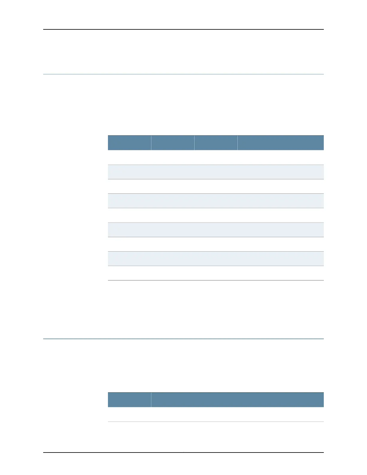
Table 83: DB-9 Connector Pinouts
DescriptionDirectionSignalPin
Carrier Detect<–DCD1
Receive Data<–RxD2
Transmit Data–>TxD3
Data Terminal Ready–>DTR4
Signal Ground—Ground5
Data Set Ready<–DSR6
Request To Send–>RTS7
Clear To Send<–CTS8
Ring Indicator<–RING9
Related
Documentation
T640 Connector Interface Panel (CIP) Description on page 19•
• Connecting the T640 Router to a Management Console or Auxiliary Device on page 210
• T640 Routing Engine Interface Cable and Wire Specifications on page 145
T640 RJ-45 Connector Pinouts for the Routing Engine ETHERNET Port
The port on the CIP labeled ETHERNET is an autosensing 10/100 millions of packets per
second (Mbps) Ethernet RJ-45 receptacle that accepts an Ethernet cable for connecting
the Routing Engine to a management LAN (or other device that supports out-of-band
management). Table 84 on page 146 describes the RJ-45 connector pinouts.
Table 84: RJ-45 Connector Pinouts
SignalPin
TX+1
Copyright © 2017, Juniper Networks, Inc.146
T640 Core Router Hardware Guide

 Loading...


