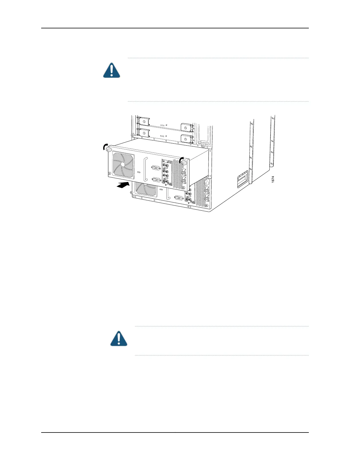
CAUTION: “Removing the T640 Power Supplies” on page 181 shows the
two-input 160-A DC power supply, but the procedure also applies to the
three-input 240-A DC power supply, four-input 240-A DC power supply, or
six-input DC power supply.
Figure 87: Reinstalling a Power Supply
Reinstalling the T640 FPCs
To reinstall FPCs (see Figure 88 on page 202):
1. Attach an electrostatic discharge (ESD) grounding strap to your bare wrist, and connect
the strap to an approved site ESD grounding point. See the instructions for your site.
2. Using the list you created when you removed the FPCs, locate the slot in the FPC card
cage in which you plan to install the FPC.
3. Inspect the slots in the FPC card cage to verify that there are no missing or bent pins
on the midplane.
4. Inspect each FPC to verify that the connectors are not misaligned or damaged.
CAUTION: When the FPC is out of the chassis, do not hold it by the ejector
handles, bus bars, or edge connectors. They cannot support its weight.
5. Lift the FPC into place and carefully align first the bottom and top of the FPC with the
guides inside the card cage. Be sure the FPC is right-side up, with the components on
the right of the FPC.
6. Gently rest the bottom edge of the FPC on the bottom edge of the slot opening, making
contact a short distance forward of the power connector.
201Copyright © 2017, Juniper Networks, Inc.
Chapter 19: Installing the T640 Router Without a Mechanical Lift

 Loading...


