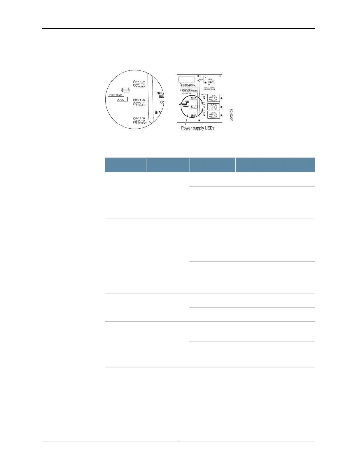
Figure 38: Three-Input 240-A DC Power Supply LEDs
Table 57 on page 101 describes the three-input 240-A DC power supply LEDs.
Table 57: Three-Input 240-A DC Power Supply LEDs
DescriptionStateColorLED
Circuit breaker is on.On steadilyGreenCB ON—One per
input
Circuit breaker is not turned on, or
host subsystem has detected a
failure and has turned the circuit
breaker off.
Off
When the power supply is correctly
set to 2-INPUT mode and INPUT 0
and INPUT 1 are properly energized,
the DC OK LED indicates that the
power supply is functioning
normally.
On steadilyBlueDC OK—One per
power supply
Power supply is starting up, is not
functioning, is not properly
installed, or is not operating
properly.
Blinking
Input is receiving voltage.On steadilyGreenINPUT
PRESENT—One
per input
Input voltage is not present.Off
Power supply has exceeded
recommended temperature.
On steadilyYellowOVER
TEMP—One per
power supply
Power supply is within the
recommended temperature or the
power supply is not on.
Off
Related
Documentation
T640 Power System Description on page 95•
• Powering On a DC-Powered T640 Router on page 239
• Maintaining the T640 Power Supplies on page 456
• T640 LED Overview on page 464
101Copyright © 2017, Juniper Networks, Inc.
Chapter 7: Power System Components and Descriptions

 Loading...


