15. Replace the clear plastic cover over the terminal studs on the faceplate.
16. Switch on the customer site circuit breakers to provide voltage to the DC power source
cables.
17. Verify that the INPUT PRESENT LEDs on the power supply faceplate are lit steadily,
indicating that the inputs are receiving power.
18. Switch the circuit breakers on the power supply to the ON position (|).
NOTE: After a power supply is powered on, it can take up to 60 seconds
forstatusindicators—such as the LEDs on the powersupply, the command
output displays, and messages on the LED display on the craft interface—to
indicate that the power supply is functioning normally. Ignore error
indicators that appear during the first 60 seconds.
19. Verify that the CB ON LEDs on the power supply faceplate are lit steadily, indicating
that the circuit breakers are on.
20. Verify that the DC OK LED on the power supply faceplate is lit steadily, indicating that
the power supply is correctly installed and is functioning properly. The DC OK LED
blinks momentarily, then lights steadily.
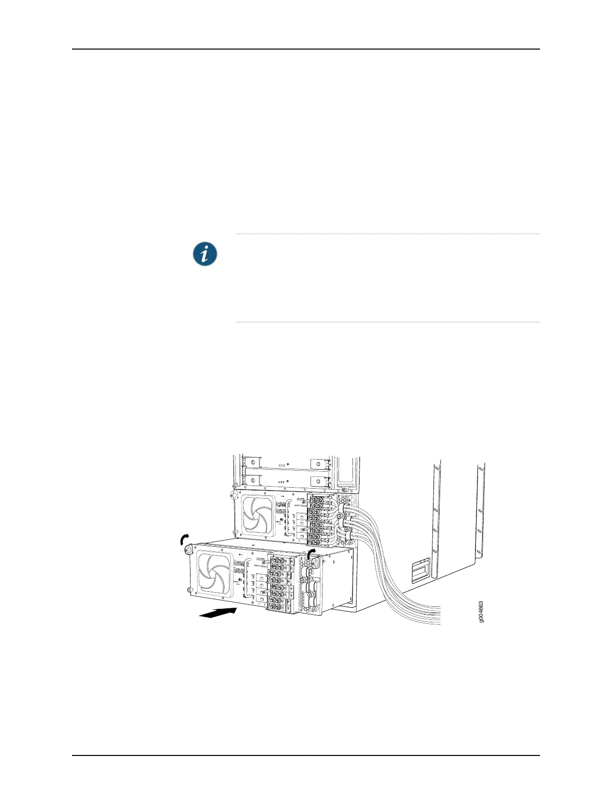
Figure 188: Installing a Four-Input 240-A DC Power Supply
Related
Documentation
T640 Power System Description on page 95•
• T640 Four-Input 240-A DC Power Supply Description on page 102
• T640 Four-Input 240-A DC Power Supply LEDs on page 103
• Troubleshooting the T640 Power System on page 476
Copyright © 2017, Juniper Networks, Inc.372
T640 Core Router Hardware Guide

 Loading...


