20. Connect the AC power cord to the AC power source.
21. Switch on the customer site circuit breakers to provide voltage to the AC power source
cables.
22. Remove the ESD grounding strap from the approved site ESD grounding point. See
the instructions for your site. Reconnect the strap to one of the ESD points on the
chassis.
23. Verify that the AC OK LED on the power supply faceplate is lit steadily, indicating that
the AC terminal block is receiving power.
24. Switch the power switch on the power supply to the ON position (|).
25. Verify that the DC OK LED on the power supply faceplate is lit steadily, indicating that
the power supply is correctly installed and is functioning properly. The DC OK LED
blinks momentarily, then lights steadily.
NOTE: After a power supply is powered on, it can take up to 60 seconds
forstatusindicators—such as the LEDs on the powersupply, the command
output displays, and messages on the LED display on the craft interface—to
indicate that the power supply is functioning normally. Ignore error
indicators that appear during the first 60 seconds.
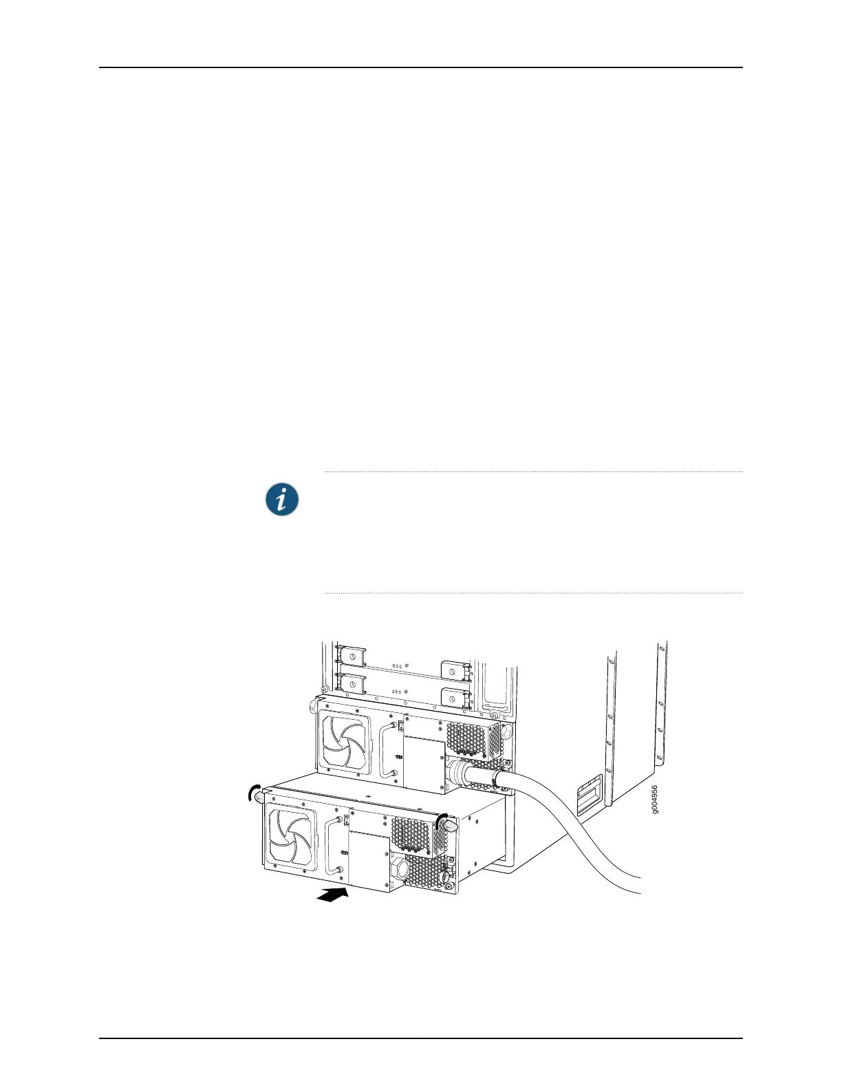
Figure 222: Installing a Three-Phase Wye AC Power Supply
Related
Documentation
T640 Three-Phase Delta and Wye AC Power Supply Description on page 106•
• T640 Three-Phase Delta and Wye AC Power Supply LEDs on page 109
415Copyright © 2017, Juniper Networks, Inc.
Chapter 29: Replacing Power System Components

 Loading...


